Batterimonitor
A PIC based battery monitor |
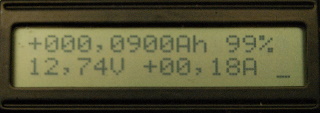
This is the source code for the firmware.
;********************************************************************** ; * ; Filename: Counter2.asm * ; Date: 2009-04-09 * ; File Version: 0.4 * ; * ; Purpose: Creates a battery-monitoring device for lead- * ; acid batteries * ; * ; Author: Anders Gustafsson (c) 2008-2010 * ; All Rights Reserved * ; Copyright: You are free to use this code for your own * ; personal use. You may not use this work for * ; commercial purposes. * ; * ; Feedback: I appreciate comments and suggestions. Please * ; send all feedback to battmeter@dalton.ax * ; * ; As published in the July-August 2010 issue of * ; Elektor: * ; http://www.elektor.com/magazines/2010/july-047-august/sailor-s-battery-meter.1392301.lynkx * ;********************************************************************** ; * ; History * ; 0.1 * ; 0.2 Elektor version * ; 0.3 Added support for "stop discharge" (RB5) * ; 0.4 Added Danish as language, plus defines to select * ; 20A or 200A fullscale. Numerous bugfixes * ; Defines for voltage to support 48V systems * ; Manual input of offset will now set "calibrated" flag * ; Limts the charge so that we do not display more than * ; the set capacity. * ; Resets the bq2018 as well when you do "set full" * ; * ;********************************************************************** ; * ; Files required: P16F690.INC * ; * ; Notes: Disable case sensitivity when compiling * ; * ; IMPORTANT! * ; In the original design, RB5 was unused and thus configured * ; as input and grounded. The Elektor article and PCB layout * ; reflects this. The current code uses RB5 as an output to * ; trigger a relay that cuts off the load after a controlled * ; discharge cycle. Either disable this feature or cut the traces * ; that connects RB5 to ground. * ;********************************************************************** ; * ; Pins: * ; RA0 - Pulses in, HDQ from bq2018 * ; RA1 - Up key * ; RA2 - Wake up from bq2018 (not yet implemented) * ; RA3 - Reset (MCLR) * ; RA5 - Down key * ; RB4 - Volts (AN10) * ; RB5 - Signal out for load testing. Goes low at 10.5V * ; RB6 - Left key * ; RB7 - NMEA out (TX) * ; RC0 - LCD E * ; RC2 - LCD Backlight * ; RC1 - LCD RS * ; RC3 - Right key * ; RC4 - LCD D4 * ; .. * ; RC7 - LCD D7 * ; RW connected to ground * ; * ;********************************************************************** ; * ; Notes: * ; Uses intosc at 8 Mhz. * ; * ; NMEA: * ; http://www.kh-gps.de/nmea.faq, * ; http://www.piclist.com/tecHREF/microchip/16F/628/UARTtest.htm * ; http://www.newmarpower.com/pdf/Manual-DCV.pdf, * ; http://www.cruzpro.com/rp30mani.pdf * ; http://vancouver-webpages.com/peter/nmeafaq.txt * ; * ; For calibration. Hold down key up whilst powering up with no * ; current through shunt. * ; A full calibration cycle takes one hour. The routine shows a * ; decrementing counter during calibration and then the calculated * ; offset in hex * ; Alternatively, short the shunt and leave the system running for * ; 1 hour or more, then read CCR, DCR, CTC, DTC, offset is then * ; (CCR-DCR)/((CTC+DTC)/4096) * ; ; For capacity testing, charge the battery to full and set counter * ; to full, Then connect a load through a relay energised by RB5 * ; When the voltage reaches 10.5, then the PIC will pull RB5 low, * ; thus releasing the load. Read the display and calculate the * ; Battery capacity as the difference between the full value and the * ; read value. * ;********************************************************************** radix dec list p=16F690 ; list directive to define processor #include; processor specific variable definitions errorlevel -302 ; suppress message 302 from list file ; ; NOTE! _MCLRE_ON for production, _MCLRE_OFF for test in MPLAB ; ; '__CONFIG' directive is used to embed configuration word within .asm file. ; The lables following the directive are located in the respective .inc file. ; See data sheet for additional information on configuration word settings. #ifdef __DEBUG __config (_INTRC_OSC_NOCLKOUT & _WDT_OFF & _PWRTE_OFF & _MCLRE_OFF & _CP_OFF & _BOR_OFF & _IESO_OFF & _FCMEN_OFF) #else __config (_INTRC_OSC_NOCLKOUT & _WDT_OFF & _PWRTE_OFF & _MCLRE_ON & _CP_OFF & _BOR_OFF & _IESO_OFF & _FCMEN_OFF) #endif ; ; Debugging defines ; ; #define NO_KEYBOARD 1 ; If we are running without a keyboard ; ; Language selection. Uncomment desired language ; ;#define ENG #define DEN ;#define SWE #ifdef ENG #define DECIMAL_POINT '.' #endif #ifdef SWE #define DECIMAL_POINT ',' #endif #ifdef DEN #define DECIMAL_POINT ',' #endif ;define CAPACITY_TEST ; If RB5 is to go low at 10.5V #define SCALE_200AH 1 ; Fullscale is 200Ah, 800 counts = 10Ah ;#define SCALE_20AH 1 ; Fullscale is 20Ah, 800 counts = 1Ah ;#define VOLTS12 ; System is 12V #define VOLTS48 ; System is 48V #ifdef VOLTS48 #define VOLTSDIV .7 ; Divisor for volts. Should be 2 for 12V where fullscale is 20.48V #endif ; set to 7 for 48V systems where fullscale is 71,68V #define RSENSE 0.01 ; Sense resistor value in ohms #ifdef VOLTS12 #define VOLTSDIV .2 #endif #define GVFC 22.2 ; VFC gain factor in Hz/V ; The define below does not work so do the maths manually for now... ;#define AFACTOR ((4096 * 1000)/(GVFC * RSENSE * 3600)) ; Multiply Charge/DeltaT by this to get mA #ifdef SCALE_20AH #define AFACTOR .5125 #define AMP_DIGITS 2 ; Amps shown as 99.999 #endif #ifdef SCALE_200AH #define AFACTOR .51251 #define AMP_DIGITS 3 ; Amps shown as 999.99 #endif ;#define NMEA ; Define this for "NMEA" output. In the end, this code would not fit in 4K ;#define IDEBUG ; ...additionally define this together with NMEA to get debug data output instead #define POLLTIME .30 ; How often (in s) to poll bq2018 and update average amps. No less than 15s! (because this kicks off the hour counter also) #define READTIME .6 ; How often (in hours) to read and zero bq2018 #define LCD_E PORTC, 0 ; How the LCD is connected #define LCD_RS PORTC, 1 #define LCD_PORT PORTC #define BACKLIGHT PORTC, 2 ; Port that controls the backlight #define UPKEY porta,1 ; Keyboard ports #define DNKEY porta,5 #define LTKEY portb,6 #define RTKEY portc,3 #define UP 1 ; Keyboard returncodes #define DN 2 #define LT 4 #define RT 8 #define TICK 0.26214 ; Unit of timing. #define IDLEWAIT 0xff ; Time (number of ticks) that current has to be below IDLEAMPS before we evaluate charge #define IDLEAMPS 0x63 ; We assume idle is when current is below this (0x63=100mA) #define DISPDELAY .4 #define MINCOUNT (POLLTIME* .229)/60 ; Timer1 kicks off every 0,26214s, multiply that by 229 and you get 60,03s #define READCOUNT (READTIME *.60 * .60 )/ POLLTIME ; Incremented by the routine that runs every polltime seconds, , 123456 ;#define READCOUNT .4 ; for testing, so that you do not have to wait 6 hours... #define CALIBHOUR 0x35ff ; Suitable time to wait for calibration to be done ; ; Register defines for the bq2018 ; #define BQ_OFFSET 0x73 #define BQ_TEMP 0x74 #define BQ_MODE 0x75 #define BQ_CTC 0x76 ; Charge time low, high is 0x77 #define BQ_DTC 0x78 ; Discharge time low, high is 0x79 #define BQ_SDC 0x7a ; Self-discharge low, high is 0x7b #define BQ_CCR 0x7c ; Charge count low, high is 0x7d #define BQ_DCR 0x7e ; Discharge count low, high is 0x7f #define BQ_WRITE 0x80 ; Add 0x80 to register to indicate write ;***** VARIABLE DEFINITIONS ; group1 UDATA 0x20 ; Note! Some work could be done here to conserve variables. Currently do some routines ; blagged from various sources use their own temp variables, so they could be conbined into fewer. cnt res 1 ; Used by bcd2a and b2bcd pto res 1 pti res 1 temp res 1 temp2 res 1 char_hi res 1 ; Used by prthex char_lo res 1 sign res 1 ; Sign bit for Ah display (+/-) bcd res 10 ; Holds output ascii string from b2bcd prtflag res 1 ; Flag is set by timer so that we get an display update voltshi res 1 ; Measured volts from ADC voltslo res 1 idlevoltshi res 1 ; Measured volts when idle, ie when current has been very low for a certain time. See below idlevoltslo res 1 idlecount res 1 ; Counter used to track idle volts amps0 res 1 ; Calculated amps from bq2018 amps1 res 1 amps2 res 1 amps3 res 1 templo res 1 ; Measured temp from bq2018, resolution is 10 degrees C dspmode res 1 ; Display mode, ie what we show on the display currently mincounter res 1 ; Counter used to kick off a routine every minute readcounter_lo res 1 ; 16 bit counter used to kick off a routine that reads and zeros the bq2018 every 6 hours readcounter_hi res 1 ; ; ; Registers used by 32-bit math ; REGA0 res 1 ;lsb REGA1 res 1 REGA2 res 1 REGA3 res 1 ;msb REGB0 res 1 ;lsb REGB1 res 1 REGB2 res 1 REGB3 res 1 ;msb REGC0 res 1 ;lsb REGC1 res 1 REGC2 res 1 REGC3 res 1 ;msb REGD0 res 1 ;lsb REGD1 res 1 REGD2 res 1 REGD3 res 1 ;msb MTEMP res 1 MCOUNT res 1 charge res 4 ; 32-bit charge counter. This holds the accumulated battery charge ; These registers are read from the bq2018 ; dcr_lo res 1 ; Discharge count register, 12.5uVh increments dcr_hi res 1 ccr_lo res 1 ; Charge count register, 12.5uVh increments ccr_hi res 1 dtc_lo res 1 ; Discharge time counter, 1 count/0.8789s dtc_hi res 1 ctc_lo res 1 ; Charge time counter, 1 count/0.8789s ctc_hi res 1 ; offset res 1 ; Calibrated offset error is based on one hour's worth of error. Subtract this from total 1/h ; ; These registers hold the previous read values so that we can calculate average current ; dcr0_lo res 1 ; Discharge count register, 12.5uVh increments dcr0_hi res 1 ccr0_lo res 1 ; Charge count register, 12.5uVh increments ccr0_hi res 1 dtc0_lo res 1 ; Discharge time counter, 1 count/0.8789s dtc0_hi res 1 ctc0_lo res 1 ; Charge time counter, 1 count/0.8789s ctc0_hi res 1 rd_err res 1 ; Read error count ; ; example of using Shared Uninitialized Data Section ; INT_VAR UDATA_SHR w_temp RES 1 ; variable used for context saving status_temp RES 1 ; variable used for context saving pclath_temp RES 1 ; variable used for context saving fsr_temp res 1 strlen res 1 ; Length of string to be printed by printstr ; LCD_VARS UDATA_SHR ; Variables used by LCD routines LCD_TMP1 RES 1 LCD_TMP2 RES 1 ; ; HDQ comms variables - begin ; timeout res 1 ;timeout flag, 0=no timeout hserdat res 1 ;high serial data register hserbit res 1 ;high serial bit counter wstack res 1 ;temp store for w register ; hcmd res 1 ;host command ; btris res 1 ;mirror trisb (stores value put in trisa, used to wiggle hdq-bit) ; ; HDQ comms variables - end ;********************************************************************************************************** ; MACROS ;********************************************************************************************************** ; Macro that sends a text to the LCD. First two bytes are row and column ; lcd_text macro text_label banksel eeadr ; change to right bank... movlw high text_label ; address bits 8-15 movwf eeadrh movlw low text_label ; address bits 0-7 movwf eeadr ; ; Address registers set up, fcall the routine ; fcall lcd_send_text banksel porta ; Leave routine in bank 0. ; endm ; ; Macro that sends a text to the LCD. No positioning ; lcd_text2 macro text_label banksel eeadr ; change to right bank... movlw high text_label ; address bits 8-15 movwf eeadrh movlw low text_label ; address bits 0-7 movwf eeadr ; ; Address registers set up, fcall the routine ; fcall lcd_send_text2 banksel porta ; Leave routine in bank 0. ; endm ;********************************************************************************************************** ; Helper macro for addressing EE ; ee_address macro text_label banksel eeadr ; Change to correct bank... movlw high text_label ; label address bits 8-15 movwf eeadrh movlw low text_label ; label address 0-7 movwf eeadr banksel 0 ; Return in bank 0 ; ; EEadr and EEadrh now hold the address of our label endm ;********************************************************************************************************** ; Helper macro for 32-bit numbers. Puts byte number 'byte' of a 32-bit literal 'var' ; into register 'reg' ; movbyte macro reg,var,byte movlw (var >>(D'08' * byte) & H'FF') movwf reg endm ;********************************************************************************************************** ; the fcall macro - do a far call and set PCLATH correctly upon return ; by Roger Froud of Amytech Ltd. fcall macro subroutine_name local here lcall subroutine_name pagesel here here: endm ;********************************************************************************************************** RESET_VECTOR CODE 0x0000 ; processor reset vector goto start ; go to beginning of program INT_VECTOR CODE 0x0004 ; interrupt vector location ;********************************************************************************************************** ; ISR ;********************************************************************************************************** INTERRUPT ; Keep the actual ISR as short as possible. ; ; Arrive here on any interrupt - first save the world... ; movwf w_temp ; save off current W register contents swapf STATUS,w ; move status register into W register movwf status_temp ; save off contents of STATUS register movf PCLATH,w ; move pclath register into W register movwf pclath_temp ; save off contents of PCLATH register movf FSR,w ; move fsr register into W register movwf fsr_temp ; save off contents of PCLATH register ; Actual isr code, determine cause of interrupt. Most likely first ; ; This is the handler for other interrupts, ie timer1 ; other_int banksel PIR1 btfss PIR1,TMR1IF ; If Timer 1 overflowed and caused the interrupt, handle it. goto other_int1 ; No timer overflow bsf prtflag,1 ; Yes, set flag to indicate to main loop that we need an update other_int1 banksel PIR1 BCF PIR1,TMR1IF ; Clear flag and continue. ; ; Catch-all for interrupt exit. Restore the world as we know it. ; exit_interrupt movf fsr_temp,w ; retrieve copy of FSR register movwf fsr ; restore pre-isr FSR register contents movf pclath_temp,w ; retrieve copy of PCLATH register movwf PCLATH ; restore pre-isr PCLATH register contents swapf status_temp,w ; retrieve copy of STATUS register movwf STATUS ; restore pre-isr STATUS register contents swapf w_temp,f swapf w_temp,w ; restore pre-isr W register contents retfie ; return from interrupt ;********************************************************************************************************** ; END ISR ;********************************************************************************************************** MAIN_PROG CODE start ; ; Main program start. Init all ports, timers etc ; ; banksel osccon movf osccon,w iorlw b'01110000' ; Set clock to 8MHz movwf osccon ; banksel ansel ; Turn off all analogue clrf ansel clrf anselh bsf anselh,ANS10 ; ANS10 is volts CLRW ; SET UP PORT banksel porta MOVWF PORTA bsf portb,5 ; Set capacity test out high movlw b'00100011' ; 0,1,5 are inputs banksel trisa movwf trisa ; Set trisa and mirror the data to btris, the register movwf btris ; that is used to wiggle the HDQ pin banksel hserbit MOVLW 08H ; LOAD BIT COUNTER MOVWF HSERBIT ; WITH 8 FOR 8 BIT banksel trisb clrf trisb ;bsf trisb,5 ; B5/AN11 bsf trisb,4 ; B4/AN10 ; ---------------------------------------------------------------------------------------------------------- ; NMEA - init USART to 4800 baud ; #ifdef NMEA fcall nmea_init ; fcall nmea_head ; fcall nmea_test ; fcall nmea_checksum #endif ; ------------------------------------ ---------------------------------------------------------------------- banksel trisc clrf trisc ;bsf trisc,2 bsf trisc,3 ; RC3 - Right key ; banksel intcon clrf intcon banksel option_reg bcf option_reg,7 ; Weak pullups are enabled on individual pins banksel wpua clrf wpua ; Disable all weak pullups bsf wpua,wpua0 ; Enable weak pull-up on A0 bsf wpua,wpua1 ; Enable weak pull-up on A1 bsf wpua,wpua5 ; Enable weak pull-up on A5 banksel wpub clrf wpub ; Disable all weak pullups bsf wpub,wpub6 ; Enable weak pull-up on B6 ; ; Init A/D converter ; banksel adcon1 movlw b'01110000' ; FRC Clock movwf adcon1 banksel adcon0 movlw b'10101001' ; Right justify, use Vdd as Vref, read AN10 movwf adcon0 fcall delay_5ms ; OK. Basic stuff done, proceed to init the LCD ; fcall lcd_init_hd44780 ; Init the LCD bcf BACKLIGHT ; Turn off backlight ; ; Print greeting text on the LCD ; lcd_text lbl_text1 lcd_text lbl_text2 lcd_text lbl_text3 fcall delay_1s ; Wait 2 s before proceeding fcall delay_1s movlw b'00000001' ; Clear display fcall lcd_send_cmd movlw 'A' fcall lcd_send_data banksel prtflag bcf prtflag,1 ; Clear the flag that triggers display update. This is later set by TMR1 banksel idlecount movlw IDLEWAIT movwf idlecount movlw MINCOUNT banksel mincounter movwf mincounter ; movbyte readcounter_lo,READCOUNT,0 movbyte readcounter_hi,READCOUNT,1 clrf dcr0_lo ; Clear out the saved values clrf dcr0_hi clrf ccr0_lo clrf ccr0_hi clrf dtc0_lo clrf dtc0_hi clrf ctc0_lo clrf ctc0_hi ; Debug data clrf dcr_lo ; Clear out values clrf dcr_hi clrf ccr_lo clrf ccr_hi clrf dtc_lo clrf dtc_hi clrf ctc_lo clrf ctc_hi clrf rd_err ; ; Debug/test data ; ; movlw 0x47 ; movwf ctc_lo ; movlw 0x24 ; movwf ctc0_lo ; movlw 0x19 ; movwf ccr_lo ; movlw 0x1 ; movwf ccr_hi ; 8000/60/2 = 100mV in 30 s ; movlw 0x8e ; movwf ccr0_lo ;movlw .33 ;movwf dcr_lo ; 8000/60/2 = 50mV in 30 s ;movlw b'01100000' ; Temp 10-20 ;movwf templo ;movlw 0xfe ; Offset ;movwf offset ;movlw .6 ; displaymode6 ;movwf dspmode ; *********************************************************************************** ; START OF CODE to initialize Timer 1 ; Set up Timer 1 to generate interrupts approx every 262.14ms. (8MHz/4/8/65536) ; This is used as a system timekeeper to generate polls every 30s and reads every 6 hours ; banksel tmr1l CLRF TMR1L ; Clear Timer1 register CLRF TMR1H banksel intcon bsf INTCON,PEIE ; Enable peripheral interrupts banksel pie1 CLRF PIE1 ; Mask all peripheral interrupts except bsf PIE1,TMR1IE ; the timer 1 interrupts. banksel pir1 CLRF PIR1 ; Clear peripheral interrupts Flags movlw B'00110000' ; Set Prescale = 8 movwf T1CON BSF T1CON,TMR1ON ; Timer1 starts to increment ;*********************************************************************************** ;END OF CODE to initialize Timer 1 ;*********************************************************************************** bsf INTCON, GIE ; enable interrupts fcall reset_counter banksel dspmode clrf dspmode ; Initial display mode is zero CLRWDT MOVLW 06H ; 00000110 = Prescaler assigned to timer 0, rate = 1/128 OPTION ; goto ourloop ; lgoto test_charge ; Test remove 12345 ; ; OK. Check if we want calibration. Ie UPKEY pressed when powering up ; movlw 'B' fcall lcd_send_data banksel porta btfsc UPKEY ; Up key pressed? goto nocalibrate lgoto calibrate ; Yes, run calibration ; no, continue nocalibrate ; lgoto do_cmd4 ; movlw 'C' fcall lcd_send_data ; ; Reset 2018 on startup, normally. Reset is done through the menu ; fcall send_break movlw 'D' fcall lcd_send_data fcall reset_bq2018 ; ;; MOVLW BQ_OFFSET ; Offset register read ;; MOVWF HSERDAT ;; fcall SNDA_IT ;; fcall hs_serva ; Read data ;; movf hserdat,w ;; movwf offset ; ; MOVLW BQ_TEMP ; Temperature register read ; MOVWF HSERDAT ; fcall SNDA_IT ; fcall hs_serva ; Read data ; movf hserdat,w ; movwf templo ; Check if calibrated and if we are, then read offset from eeprom ; clrf offset ; Zero offset ee_address flags fcall read_flash_ee ; read flags from eeprom into w movwf rega0 btfss rega0,0 ; Check calibrated bit goto ourloop ; Not calibrated, leave offset at zero ee_address stored_offset ; Valid calibration, read offset from eeprom fcall read_flash_ee ; movwf offset ; and put in offset register movlw 'E' fcall lcd_send_data ;********************************************************************************************************** ; MAIN LOOP ;********************************************************************************************************** ; ; All init done, enter loop that never ends ; ourloop ;--------------- Test loop ----------------- ;loop2 ; bcf portc,0 ; Wiggle scope trigger ; bsf portc,0 ; ; ; fcall send_break ; banksel hserbit ; MOVLW 08H ;LOAD BIT COUNTER ; MOVWF HSERBIT ;WITH 8 FOR 8 BIT ; MOVLW 74H ; read TMP/CLR register ; MOVWF HSERDAT ; CALL SNDA_IT ; fcall hs_serva ; goto loop2 ; fcall send_break ; ; movlw dcr_lo ; Set up address to receive data ; movwf fsr ; in fsr ; movlw BQ_DCR ; Set up address of discharge low register ; fcall read_16 ; fcall routine to read it ; ; movlw ccr_lo ; Set up address to receive data ; movwf fsr ; in fsr ; movlw BQ_CCR ; Set up address of charge low register ; fcall read_16 ; fcall routine to read it ; ; movlw dtc_lo ; Set up address to receive data ; movwf fsr ; in fsr ; movlw BQ_DTC ; Set up address of discharge time low register ; fcall read_16 ; fcall routine to read it ; ; movlw ctc_lo ; Set up address to receive data ; movwf fsr ; in fsr ; movlw BQ_CTC ; Set up address of discharge low register ; fcall read_16 ; fcall routine to read it ;goto loop2 ;--------------- Test loop ----------------- ; ; Check our "keyboard". We have four buttons: Up, Down, left, right ; left and right steps through the top level displays. ; ;lgoto maintenance ;fcall poll check_key ;movlw 'F' ;fcall lcd_send_data fcall getkey ; Check for key btfss status,C goto check_key1 ; No key, skip to loop check movwf regd0 ; We have a key, save it btfss regd0,2 ; LT ie 4? goto check_key_not_left decf dspmode,1 ; Decrement displaymode btfss dspmode,7 ; Rolled over? goto check_key1 ; no movlw .7 ; yes, put back to 7 movwf dspmode goto check_key1 check_key_not_left btfss regd0,3 ; RT ie 8? goto check_key_not_right incf dspmode,1 ; Increment the display mode (0..7) btfss dspmode,3 ; reached end? goto check_key_not_right ; no clrf dspmode ; yes, back to zero ; goto check_key1 check_key_not_right check_key1 ;movlw 'G' ;fcall lcd_send_data banksel prtflag btfss prtflag,1 ; Do we need to print/display? Flag is set by Timer1 interrupt. goto ourloop ; no, loop forever ; Yes, print bcf prtflag,1 ; and clear print flag ;movlw 'H' ;fcall lcd_send_data ; ; Things that happen on every TICK ; ; Check events that should happen every minute and every hour ; check_minute banksel mincounter decfsz mincounter,f ; Has one minute elapsed? goto check_minute1 ; no, not yet movlw MINCOUNT ; yes, prime counter movwf mincounter ; and jump to routine ;movlw 'I' ;fcall lcd_send_data ; fcall goes here! fcall poll poll_rtn ;movlw 'J' ;fcall lcd_send_data ; Has six hours elapsed? movf readcounter_lo,f ; 16-bit decrement skpnz decf readcounter_hi,f decf readcounter_lo,f btfss readcounter_hi,7 ; Wrapped around? goto check_hour1 ; no, not yet ;movlw 'K' ;fcall lcd_send_data ; yes, prime counter movbyte readcounter_lo,READCOUNT,0 movbyte readcounter_hi,READCOUNT,1 ; and jump to routine ; lgoto read check_minute1 check_hour1 ; ; Data aquisition stuff ; ; ; Read AD10 to get voltage ; read_voltage ; Store old voltage to calculate difference banksel voltslo ; Old voltage -> REGB movf voltslo,w movwf regb0 movf voltshi,w movwf regb1 clrf regb2 clrf regb3 banksel adcon0 ; OK. Read it movlw b'10101001' ; Right justify, Vdd Vref, an10 movwf adcon0 fcall delay_5us fcall delay_5us bsf adcon0,go btfsc adcon0,go goto $-1 banksel adresh ; Note that adresh/adresl are in different banks! movf adresh,w banksel voltshi movwf voltshi movwf rega1 banksel adresl movf adresl,w banksel voltslo movwf voltslo movwf rega0 ; New voltage -> REGA clrf rega2 clrf rega3 fcall subtract ; Calculate change in voltage REGA-REGB -> REGA fcall absa ; absolute value of change is in REGA movf rega1,1 ; If msb is above zero then skip btfss STATUS,z goto not_samevolts ; Snippet: if (A > CONST) ; Inputs: rega0 movf rega0, W ; Check value of lsb sublw 5 ; W = 5-A. 5 is 0.1V btfsc STATUS, C ; Check for borrow.. goto v_false ; C=1, A<=CONST, false cond'n ; Place result TRUE code here. goto not_samevolts v_false: ; Delta volts is below what we consider idle movf idlecount,1 ; Idle count zero? btfsc STATUS,z goto xyzzy decf idlecount,1 ; Decrement idle counter. goto xyzzy not_samevolts ; Voltage has changed movlw IDLEWAIT ; We are not idle, prime idle counter so that we start counting down again movwf idlecount xyzzy bcf status,c ; Clear carry banksel voltslo fcall delay_5us ; Give ADC time to breathe #ifdef CAPACITY_TEST ; ; Check for end voltage (10.5) in a capacity test, 10.5V = 525 ; ; Snippet: 16-bit if(A <= B), A = Volts, B = 10.5 (525, 0x20D) ; Inputs: A_high, A_low, B_high, B_low ; Strategy: Do a 16-bit B-A and watch for borrow off 16th bit. ; ; Note that 10.5 is hardcoded, but it is OK. It is a constant like pi, e or c. movf voltslo, W sublw 0x0d ; W = B-A (low) movlw 0x00 ; Clear W btfss STATUS, C ; Check for carry on low bytes. movlw 0x01 ; C=0, A_low < B_low, needed to borrow (sub 1 from high) ; C=1, B_low > A_low, do not sub 1 from high byte addwf voltshi, W ; Adding 1 to B is like subtracting 1 from A (if W=1) btfsc STATUS, C ; If A_high == FF, can borrow and not realize goto false ; false cond'n sublw 0x02 ; W = B-A (high) - borrow if applicable btfss STATUS, C ; Check whole 16-bit addition for borrow goto false ; C=0, result needs borrow from 17th bit. ; C=1, result true ; Place result TRUE code here. bcf portb,5 ; Voltage at or below 10.5, pull pin down to disconnect load goto end_if false: ; Place result FALSE code here. end_if: ; end of snippet #endif ; ; ; Calculate average current, Note that the error will be substantial for small ; currents! ; First calculate delta t ; movf ctc_lo,W ; Get ctc into REGA movwf rega0 movf ctc_hi,W movwf rega1 clrf rega2 clrf rega3 movf ctc0_lo,w ; Get ctc0 into REGB movwf regb0 movf ctc0_hi,w movwf regb1 clrf regb2 clrf regb3 fcall subtract ; Subtract REGA-REGB-> REGA movf dtc_lo,w ; Get dtc into REGB movwf regb0 movf dtc_hi,w movwf regb1 clrf regb2 clrf regb3 fcall add ; Add REGA+REGB-> REGA movf dtc0_lo,w ; Get dtc0 into REGB movwf regb0 movf dtc0_hi,w movwf regb1 clrf regb2 clrf regb3 fcall subtract ; Delta t now in REGA, save it in regd movf rega0,w movwf regd0 movf rega1,w movwf regd1 movf rega2,w movwf regd2 movf rega3,w movwf regd3 ; ; Then calculate the change in charge ; movf ccr_lo,W ; Get ccr into REGA movwf rega0 movf ccr_hi,W movwf rega1 clrf rega2 clrf rega3 movf ccr0_lo,w ; Get ccr0 into REGB movwf regb0 movf ccr0_hi,w movwf regb1 clrf regb2 clrf regb3 fcall subtract ; Subtract REGA-REGB-> REGA movf dcr_lo,w ; Get dcr into REGB movwf regb0 movf dcr_hi,w movwf regb1 clrf regb2 clrf regb3 fcall subtract ; Subtract REGA-REGB-> REGA movf dcr0_lo,w ; Get dcr0 into REGB movwf regb0 movf dcr0_hi,w movwf regb1 clrf regb2 clrf regb3 fcall add ; Change in charge now in rega ; ; Multiply to get real amps goes here, multiply to give milliamps ; Actual factor is above ; movbyte regb0,AFACTOR,0 movbyte regb1,AFACTOR,1 movbyte regb2,AFACTOR,2 movbyte regb3,AFACTOR,3 fcall multiply movf regd0,w ; Get delta t into regb movwf regb0 movf regd1,w movwf regb1 movf regd2,w movwf regb2 movf regd3,w movwf regb3 fcall divide ; rega / regb -> rega movf rega0,w ; Store calculated amps movwf amps0 movf rega1,w movwf amps1 movf rega2,w movwf amps2 movf rega3,w movwf amps3 ; On a lead-acid battery, the idle voltage corresponds roughly to charge (especially if you adjust for temperature) ; the trick is that you need to measure when the battery has been idle for a while. Ideally hours, but ; for now we assume that if voltage has been within 0.1V for 60s and current is small, then take a sample. ; ; ; Are we idle? Idle is defined as a current less than 100ma, ie amps1..3 = 0, amps0 = 0x63 or below ; banksel amps0 movf amps0,w ; Get amps into rega movwf rega0 movf amps1,w movwf rega1 movf amps2,w movwf rega2 movf amps3,w movwf rega3 fcall absa ; Make absolute movf rega3,1 ; Amps hi zero? btfss status,z goto notidle ; Zero flag not set, current not idle movf rega2,1 ; Amps hi zero? btfss status,z goto notidle ; Zero flag not set, current not idle movf rega1,1 ; Amps hi zero? btfss status,z goto notidle ; Zero flag not set, current not idle movlw IDLEAMPS ; Our definition of idle (0x63 = 100mA) subwf rega0,0 ; subtract and store in w btfsc status,c ; if w<=ampslo, then carry will be set goto notidle ; ; Current draw is less than what we define as "idle", check idle counter, if zero, then store idle volts ; banksel idlecount movf idlecount,1 ; Idle count zero? btfss STATUS,z goto notidle banksel voltslo movf voltslo,W ; Low current and voltage has been the same for xx loops, grab lower part of voltage movwf idlevoltslo ; and store as idle volts value movf voltshi,W ; Same for high part movwf idlevoltshi ; notidle done_amps ; ; Read bq2018 to get temperature. It is held in bits7..5 in register 74 (tmp/clr) ; ; Temp Value (hex) SDR Count Rate ; <0° 0h × 1/8 ; 0–10° 1h × 1/4 ; 10–20° 2h × 1/2 ; 20–30° 3h 1 count/hr. ; 30–40° 4h × 2 ; 40–50° 5h × 4 ; 50–60° 6h × 8 ; >60° 7h × 16 ; read_temperature ; ;DISPLAY_STUFF CODE ;----------------------------------------------------------------------------------------------------- ; Done aquiring data, display it according to selected display mode: ; 0 - 999.999Ah 99%, 9,99V +99,99A ; 1 - 999.999999Ah, 9,99V +99,99A ; 2 - 99,99C ; 3 - ; Page-safe jumptable from AN556. Checks for carry when adding offset and ; adjusts PCLATH accordingly banksel dspmode movf dspmode,w ; Get display mode in W andlw .7 ; Make sure it is within bounds (0..7) movwf rega0 ; save in temp register movlw LOW dsptable ; Get low address of table addwf rega0,F ; add offset movlw HIGH dsptable ; Get high 5 bits of address btfsc status,c ; Did we cross a page? addlw 1 ; Yes, increment high address movwf pclath ; Load high address in latch movf rega0,w movwf pcl ; Load computed offset into program counter dsptable goto displaymode0 ; Jump table to display mode handlers goto displaymode1 goto displaymode2 goto displaymode3 goto displaymode4 goto displaymode5 goto displaymode6 goto displaymode7 ;---------------------------------------------------------------------------------------------------------------------------- ; Display mode 0 ; ; 999.999Ah 99% ; 9,99V +99,99A displaymode0 movlw b'00000001' ; Clear display fcall lcd_send_cmd banksel charge movf charge,W ; Get charge into REGA movwf rega0 movf charge+1,W movwf rega1 movf charge+2,W movwf rega2 movf charge+3,W movwf rega3 movf ccr_lo,w ; Get charge count into REGB movwf regb0 movf ccr_hi,w movwf regb1 clrf regb2 ; ccr is a 16-bit value so zero the upper 16 bita clrf regb3 fcall add ; Add up REGA+REGB-> REGA movf dcr_lo,w ; Get discharge count into REGB movwf regb0 movf dcr_hi,w movwf regb1 clrf regb2 ; dcr is a 16-bit value so zero the upper 16 bita clrf regb3 fcall subtract ; REGA - REGB -> REGA ; 100mV/1h = 8000 counts. 100mV / 0.01 ohm is 10A ; 100mV/1h = 8000 counts. 100mV / 0.001 ohm is 100A #ifdef SCALE_20AH ; For 20Ah max scale movlw .8 ; adjust: 8000 = 10Ah, so divide by 8, then multiply by 10 when presenting movwf regb0 clrf regb1 clrf regb2 clrf regb3 fcall divide #endif #ifdef SCALE_200AH ; For 200Ah max scale movf rega0,w ; Save value REGA -> REGD movwf regd0 movf rega1,w movwf regd1 movf rega2,w movwf regd2 movf rega3,w movwf regd3 ; movlw .4 ; Divide by 4 to get one quarter movwf regb0 ; REGA = REGA /4 clrf regb1 clrf regb2 clrf regb3 fcall divide movf regd0,w ; Grab value movwf regb0 movf regd1,w movwf regb1 movf regd2,w movwf regb2 movf regd3,w movwf regb3 fcall add ; REGA = REGA + REGB (REGA = REGA * 1.25) #endif fcall b2bcd ; convert 32-bit binary in REGA to 10 bcd fcall bcd2a ; convert 10 bcd to 10 ascii movlw b'00000010' ; Display/curs home fcall lcd_send_cmd movf sign,W fcall lcd_send_data movlw .3 ;3d bytes of ascii, ie 3 digits "999" movwf strlen movlw bcd+5 ;based at this location fcall printstr ; movlw DECIMAL_POINT ;',' fcall lcd_send_data ; movlw .2 ;2d bytes of ascii, ie 2 digits ".00Ah" movwf strlen movlw bcd+8 ;based at this location fcall printstr ; movlw 'A' fcall lcd_send_data movlw 'h' fcall lcd_send_data movlw ' ' fcall lcd_send_data movlw ' ' fcall lcd_send_data movlw ' ' fcall lcd_send_data fcall delay_5ms ; ; determine approx battery left from idle voltage and display ; fcall find_charge ; Find_charge returns charge in w as two nibbles, print them. banksel temp movwf temp andlw 0xf0 ;Mask lsb to leave msb movwf temp2 bcf status,c ; Clear carry rrf temp2,1 ; Rotate to get msb rrf temp2,1 rrf temp2,1 rrf temp2,0 addlw 0x30 ; '0' fcall lcd_send_data movf temp,w andlw 0x0f ;Mask msb to leave lsb addlw 0x30 ; '0' fcall lcd_send_data movlw '%' fcall lcd_send_data movlw ' ' fcall lcd_send_data ; ; Convert & print voltage ; display_voltage banksel voltslo movf voltslo,W ; Get volts movwf rega0 movf voltshi,W movwf rega1 clrf rega2 clrf rega3 movlw VOLTSDIV movwf regb0 ; 1024 is 20.48V so multiply by two (Or you could rotate, but we have the multiply routine anyway..) clrf regb1 clrf regb2 clrf regb3 fcall multiply fcall b2bcd ; convert to 32-bit binary to 10 bcd fcall bcd2a ; convert 10 bcd to 10 ascii movlw 0x80+0x40 ; Goto first pos of line 2 fcall lcd_send_cmd ; ; Convert and print "1500" as "15.0V" ; movlw .2 ;2d bytes of ascii movwf strlen movlw bcd+6 ;based at this location fcall printstr ; movlw DECIMAL_POINT ;',' fcall lcd_send_data ; movlw .2 ;2d bytes of ascii movwf strlen movlw bcd+8 ;based at this location fcall printstr ; ; movlw 'V' fcall lcd_send_data movlw ' ' fcall lcd_send_data ; ; Convert & print current ; display_amps banksel amps0 movf amps0,W ; Get amps movwf rega0 movf amps1,W movwf rega1 movf amps2,W movwf rega2 movf amps3,W movwf rega3 fcall b2bcd ; convert to 32-bit binary to 10 bcd fcall bcd2a ; convert 10 bcd to 10 ascii ; ; Convert and print "2048" as "+20.48A" ; movf sign,w fcall lcd_send_data ; Buffer data is 0123456789 -> 0123456.789A movlw AMP_DIGITS ;2d bytes of ascii for 20A, 3d bytes of ASCII for 200A (.2) movwf strlen movlw bcd+(6-AMP_DIGITS+1) ;based at this location (5 for xx.xxx, 4 for xxx.xx) fcall printstr ; movlw DECIMAL_POINT ; ',' fcall lcd_send_data ; movlw 5-AMP_DIGITS ;3d bytes of ascii for 20A, 2d bytes for 200A (.3) movwf strlen movlw bcd+7 ;based at this location fcall printstr ; movlw 'A' fcall lcd_send_data movlw ' ' fcall lcd_send_data ;; ;; Debug stuff to show display mode ;; ; banksel dspmode ; movf dspmode,W ; addlw '0' ; fcall lcd_send_data lgoto ourloop ;---------------------------------------------------------------------------------------------------------------------------- ; Display mode 1 - Show temperature and the temperature/clear register ; ; 99C (xx) ; displaymode1 display_temperature banksel templo movf templo,W ; Get temperature/clear into w. MS 3 bits is temp andlw b'11100000' ; Mask movwf rega0 bcf status,c ; Clear carry swapf rega0,1 rrf rega0,1 ; move bits 7..5 to 3..0 clrf rega1 clrf rega2 clrf rega3 movlw .10 ; Multiply by 10. Thus we display the temperature as the midpoint in every interval, ie movwf regb0 ; the interval 20-30 is shown as 25C clrf regb1 clrf regb2 clrf regb3 fcall multiply movlw .5 ; Subtract 5 movwf regb0 clrf regb1 clrf regb2 clrf regb3 fcall subtract fcall b2bcd ; convert to 32-bit binary to 10 bcd fcall bcd2a ; convert 10 bcd to 10 ascii movlw b'00000001' ; Clear display fcall lcd_send_cmd movlw b'00000010' ; Display/curs home fcall lcd_send_cmd ; ; Convert and print "15" as "15" ; movlw .2 ;2d bytes of ascii movwf strlen movlw bcd+8 ;based at this location fcall printstr ; ; movlw 0xdf fcall lcd_send_data movlw 'C' fcall lcd_send_data movlw ' ' fcall lcd_send_data movlw '(' fcall lcd_send_data movf templo,w fcall prthex ; Display data movlw ')' fcall lcd_send_data lgoto ourloop ;---------------------------------------------------------------------------------------------------------------------------- ; Display mode 2 - Show the counters in hex ; ; Ct XXXX Cc XXXX ; Dt XXXX Dc XXXX displaymode2 movlw b'00000010' ; Display/curs home fcall lcd_send_cmd movlw 'C' fcall lcd_send_data movlw 't' fcall lcd_send_data movlw ' ' fcall lcd_send_data ; movf ctc_hi,w fcall prthex ; Display data movf ctc_lo,w fcall prthex ; Display data movlw ' ' fcall lcd_send_data movlw 'C' fcall lcd_send_data movlw 'c' fcall lcd_send_data movlw ' ' fcall lcd_send_data movf ccr_hi,w fcall prthex ; Display data movf ccr_lo,w fcall prthex movlw 0x80+0x40 ; Goto first pos of line 2 fcall lcd_send_cmd movlw 'D' fcall lcd_send_data movlw 't' fcall lcd_send_data movlw ' ' fcall lcd_send_data ; movf dtc_hi,w fcall prthex ; Display data movf dtc_lo,w fcall prthex ; Display data movlw ' ' fcall lcd_send_data movlw 'D' fcall lcd_send_data movlw 'c' fcall lcd_send_data movlw ' ' fcall lcd_send_data movf dcr_hi,w fcall prthex ; Display data movf dcr_lo,w fcall prthex lgoto ourloop ;---------------------------------------------------------------------------------------------------------------------------- ; Display mode 3 ; ; Amps (hex) ; Amps (ascii) displaymode3 movlw b'00000001' ; Clear display fcall lcd_send_cmd lcd_text lbl_amps banksel amps0 movf amps3,W ; Print amps in hex fcall prthex movf amps2,W fcall prthex movf amps1,W fcall prthex movf amps0,W fcall prthex movlw 0x80+0x40 ; Goto first pos of line 2 fcall lcd_send_cmd movf sign,w fcall lcd_send_data movf amps0,W ; Print amps in decimal movwf rega0 movf amps1,W movwf rega1 movf amps2,W movwf rega2 movf amps3,W movwf rega3 fcall b2bcd ; convert to 32-bit binary to 10 bcd fcall bcd2a ; convert 10 bcd to 10 ascii movlw .10 ;10d bytes of ascii movwf strlen movlw bcd ;based at this location fcall printstr lgoto ourloop displaymode4 ;---------------------------------------------------------------------------------------------------------------------------- ; Display mode 4 - Raw (non-adjusted) charge, plus mincounter and readcounter ; ; 9999999999mAh ; XX XXXX movlw b'00000001' ; Clear display fcall lcd_send_cmd banksel charge movf charge,W ; Get charge into REGA movwf rega0 movf charge+1,W movwf rega1 movf charge+2,W movwf rega2 movf charge+3,w movwf rega3 movf ccr_lo,w ; Get charge count into REGB movwf regb0 movf ccr_hi,w movwf regb1 clrf regb2 ; ccr is a 16-bit value so zero the upper 16 bita clrf regb3 fcall add ; Add up REGA+REGB-> REGA movf dcr_lo,w ; Get discharge count into REGB movwf regb0 movf dcr_hi,w movwf regb1 clrf regb2 ; dcr is a 16-bit value so zero the upper 16 bita clrf regb3 fcall subtract ; REGA - REGB -> REGA fcall b2bcd ; convert 32-bit binary in REGA to 10 bcd fcall bcd2a ; convert 10 bcd to 10 ascii movlw b'00000010' ; Display/curs home fcall lcd_send_cmd movf sign,W fcall lcd_send_data movlw .10 ;10d bytes of ascii, ie 10 digits "999Ah" movwf strlen movlw bcd ;based at this location fcall printstr ; movlw 'A' fcall lcd_send_data movlw 'h' fcall lcd_send_data movlw ' ' fcall lcd_send_data fcall delay_5ms movlw 0x80+0x40 ; Goto first pos of line 2 fcall lcd_send_cmd movf mincounter,W fcall prthex movlw ' ' fcall lcd_send_data movf readcounter_hi,W fcall prthex movf readcounter_lo,W fcall prthex lgoto ourloop displaymode5 ;---------------------------------------------------------------------------------------------------------------------------- ; Display mode 5 - Offset and serial error counter, idle volts, selfdischarge counter ; ; Of XX Er XX ; 99,99V SD XXXX movlw b'00000001' ; Clear display fcall lcd_send_cmd movlw 'O' fcall lcd_send_data movlw 'f' fcall lcd_send_data movlw ' ' fcall lcd_send_data movf offset,W fcall prthex movlw ' ' fcall lcd_send_data movlw 'E' fcall lcd_send_data movlw 'r' fcall lcd_send_data movlw ' ' fcall lcd_send_data movf rd_err,W fcall prthex movlw 0x80+0x40 ; Goto first pos of line 2 fcall lcd_send_cmd movf idlevoltslo,W ; Get idlevolts movwf rega0 movf idlevoltshi,W movwf rega1 clrf rega2 clrf rega3 fcall b2bcd ; convert to 32-bit binary to 10 bcd fcall bcd2a ; convert 10 bcd to 10 ascii ; ; Convert and print saved idle volts ; movlw .2 ;2d bytes of ascii movwf strlen movlw bcd+6 ;based at this location fcall printstr ; movlw DECIMAL_POINT ;',' fcall lcd_send_data ; movlw .2 ;2d bytes of ascii movwf strlen movlw bcd+8 ;based at this location fcall printstr ; ; movlw 'V' fcall lcd_send_data movlw ' ' fcall lcd_send_data movlw 'S' fcall lcd_send_data movlw 'D' fcall lcd_send_data movlw 'C' fcall lcd_send_data movlw ' ' fcall lcd_send_data fcall send_break movlw regd0 ; Set up address to receive data movwf fsr ; in fsr movlw BQ_SDC ; Set up address of discharge time low register fcall read_16 ; fcall routine to read it movf regd1,W fcall prthex movf regd0,W fcall prthex lgoto ourloop ; ; Rest of modes, just show mode for now ; displaymode6 movlw b'00000001' ; Clear display fcall lcd_send_cmd lcd_text lbl_dspmode banksel dspmode movf dspmode,W addlw '0' fcall lcd_send_data lgoto ourloop displaymode7 movlw b'00000001' ; Clear display fcall lcd_send_cmd lcd_text lbl_maint ; "Maintenance" movlw 0x80+0x40 ; Goto first pos of line 2 fcall lcd_send_cmd lcd_text2 lbl_maint3a ; "Enter.." kbloop movlw 0x80+0x40 ; Goto first pos of line 2 fcall lcd_send_cmd fcall getkey btfss status,c ; Carry set if key was pressed goto kbloop ; No key.. movwf rega0 ;fcall prthex btfss rega0,0 ; UP? goto kbloop_not_up banksel dspmode clrf dspmode goto ourloop kbloop_not_up btfss rega0,1 ; DN? goto kbloop ;fcall delay_1s ;goto ourloop ; Nope lgoto maintenance ;goto ourloop BQ2018_STUFF CODE ;************************************************ SUBROUTINES ******************************************************* ; ; Poll - Subroutine that gets fcalled approximately twice a minute (OK every 30,015s) ; Read counters from bq2018 ; ; ; http://www.datasheetcatalog.org/datasheet/texasinstruments/bq26200.pdf ; "For self-discharge calculation, the self-discharge count register (SCR) counts at a rate of 1 count every hour ; at a nominal 25°C. The SCR count rate doubles approximately every 10°C up to 60°C. The SCR count rate is ; halved every 10°C below 25°C down to 0°C. The value in SCR is useful in estimating the battery self-discharge ; based on capacity and storage temperature conditions poll movf dcr_lo,w ; Save the old values movwf dcr0_lo movf dcr_hi,w movwf dcr0_hi movf ccr_lo,w movwf ccr0_lo movf ccr_hi,w movwf ccr0_hi movf dtc_lo,w movwf dtc0_lo movf dtc_hi,w movwf dtc0_hi movf ctc_lo,w movwf ctc0_lo movf ctc_hi,w movwf ctc0_hi ; Read new values here bcf INTCON, GIE ; Disable interrupts fcall send_break movlw dcr_lo ; Set up address to receive data movwf fsr ; in fsr movlw BQ_DCR ; Set up address of discharge low register fcall read_16 ; fcall routine to read it fcall Delay_5us movlw ccr_lo ; Set up address to receive data movwf fsr ; in fsr movlw BQ_CCR ; Set up address of charge low register fcall read_16 ; fcall routine to read it fcall Delay_5us fcall send_break movlw dtc_lo ; Set up address to receive data movwf fsr ; in fsr movlw BQ_DTC ; Set up address of discharge time low register fcall read_16 ; fcall routine to read it ; fcall Delay_5us movlw ctc_lo ; Set up address to receive data movwf fsr ; in fsr movlw BQ_CTC ; Set up address of discharge low register fcall read_16 ; fcall routine to read it MOVLW BQ_TEMP ; Temperature register read MOVWF HSERDAT fcall SNDA_IT fcall hs_serva ; Read data movf hserdat,w movwf templo bsf INTCON, GIE ; enable interrupts ; bcf BACKLIGHT ; Turn off backlight ;----------------------------------------------------------------------------------------------------- ; Dump out NMEA data over the serial port ; #ifdef NMEA fcall nmea_data #endif return ;----------------------------------------------------------------------------------------------------- ; Read counters from bq2018 and zero them. Add up to total charge ; ; Read values here, then zero counters ; read fcall send_break movlw dcr_lo ; Set up address to receive data movwf fsr ; in fsr movlw BQ_DCR ; Set up address of discharge low register fcall read_16 ; fcall routine to read it movlw ccr_lo ; Set up address to receive data movwf fsr ; in fsr movlw BQ_CCR ; Set up address of charge low register fcall read_16 ; fcall routine to read it movlw dtc_lo ; Set up address to receive data movwf fsr ; in fsr movlw BQ_DTC ; Set up address of discharge time low register fcall read_16 ; fcall routine to read it movlw ctc_lo ; Set up address to receive data movwf fsr ; in fsr movlw BQ_CTC ; Set up address of discharge low register fcall read_16 ; fcall routine to read it ; ; Values read ; movlw BQ_TEMP+BQ_WRITE ; tmp/clr register movwf hserdat fcall snda_it movlw b'00011011' ; reset all registers, except SCR movwf hserdat fcall snda_it ; OK. Charge and discharge in dcr and ccr. Start calculating ; Calculate running time since last reset movf ctc_lo,w ; Get charge time into REGA movwf rega0 movf ctc_hi,w movwf rega1 clrf rega2 ; ctc is a 16-bit value so zero the upper 16 bita clrf rega3 movf dtc_lo,w ; Get discharge time into REGB movwf regb0 movf dtc_hi,w movwf regb1 clrf regb2 ; dtc is a 16-bit value so zero the upper 16 bita clrf regb3 fcall add ; CTC + DTC -> REGA. We should store this as we will need it for SDC calculation later ; Now that we have the running time, calculate hours by dividing by 4096, then ; multiply offset by hours. The actual calculation is done the other way around though ; Ie the offset is multiplied by the time, then the result is divided by 4096. This ; yields better accuracy and worstcase 6 * 128 * 65535 * 2 will not overflow a 32-bit integer ; Offset is a 8-bit value, if positive say 0x01 it needs to be extended to 0x00000001, if negative ; say 0xff (or -1), then it needs to be extended into 0xffffffff movf offset,w ; Get offset (positive or negative) into REGB movwf regb0 btfsc offset,7 ; Is offset negative goto offset_negative ; Yes clrf regb1 ; No, positive offset, zero out upper 24 bits clrf regb2 clrf regb3 goto offset_calc offset_negative ; Negative offset, make all upper 24 bits ones movlw 0xff movwf regb1 movwf regb2 movwf regb3 offset_calc fcall multiply ; Running time times 4096 * offset -> REGA clrf regb0 ; Put 4096 (1000h) in REGB clrf regb2 clrf regb3 movlw 0x10 movwf regb1 fcall divide ; REGA / 4096 -> REGA. REGA now holds time-adjusted offset fcall movab ; REGA -> REGB movf charge,W ; Get charge into REGA movwf rega0 movf charge+1,W movwf rega1 movf charge+2,W movwf rega2 movf charge+3,W movwf rega3 fcall subtract ; Charge - Offset -> REGA movf rega0,w ; Save it movwf charge movf rega1,w movwf charge+1 movf rega2,w movwf charge+2 movf rega3,w movwf charge+3 ; We have now adjusted for offset ; Add the new charge/discharge. Start by adjusting charge for efficiency banksel ccr_lo movf ccr_lo,w ; Get charge count into REGA movwf rega0 movf ccr_hi,w movwf rega1 clrf rega2 ; ccr is a 16-bit value so zero the upper 16 bita clrf rega3 ee_address efficiency ; Get efficiency into REGB movlw .1 ;1d bytes movwf strlen movlw regb0 fcall copybytes clrf regb1 ; ccr is a 16-bit value so zero the upper 16 bits clrf regb2 clrf regb3 fcall multiply ; REGA * REGB-> REGA movf rega1,w ; Shift everyting one byte, thus dividing by 256 movwf rega0 movf rega2,w movwf rega1 movf rega3,w movwf rega2 clrf rega3 ; REGA now holds adjusted charge ;fcall add ; Add Adjusted charge to total delta charge movf dcr_lo,w ; Get discharge count into REGB movwf regb0 movf dcr_hi,w movwf regb1 clrf regb2 ; dcr is a 16-bit value so zero the upper 16 bits clrf regb3 fcall subtract ; Subtract discharge from total delta, result in REGA movf charge,W ; Get total charge into REGB movwf regb0 movf charge+1,W movwf regb1 movf charge+2,W movwf regb2 movf charge+3,W movwf regb3 fcall add ; Total charge + delta charge -> REGA movf rega0,w movwf charge movf rega1,w movwf charge+1 movf rega2,w movwf charge+2 movf rega3,w movwf charge+3 ; New total charge stored ; Self discharge check goes here. Read the SCR ; Assuming 100Ah and 5%, self-discharge @20C is 5Ah. If 1Ah = 800 (assuming a 0,01ohm shunt) ; then self-discharge is 4000/month or 132/day. So we wait until SCR is above 24 and when it is ; we multiply by SCR, subtract from the total charge and zero SCR. banksel rega0 ee_address capacity ; Read capacity from eeprom movlw .4 ; 4d bytes movwf strlen movlw rega0 fcall copybytes ; Copy capacity to REGBA ee_address discharge ; Read discharge from eeprom fcall read_flash_ee movwf regb0 ; Discharge is one byte, 100 = 100% clrf regb1 clrf regb2 clrf regb3 call multiply ; capacity * discharge -> REGA movbyte regb0,.12132,0 ; Divide by 100 and factor to convert self-discharge, expressed in %/month to movbyte regb1,.12132,1 ; value per six hours, ie our read interval 30,33 * 4, ie 100 * 30,33 * 4 = 12132 movbyte regb2,.12132,2 movbyte regb3,.12132,3 call divide ; Self-discharge value for six hours now in REGA fcall send_break movlw regb0 ; Set up address to receive data movwf fsr ; in fsr movlw BQ_SDC ; Set up address of discharge time low register fcall read_16 ; fcall routine to read it into REGB call multiply ; Total self-discharge now in REGA fcall movab ; REGA -> REGB test_charge movf charge,W ; Get total charge into REGA movwf rega0 movf charge+1,W movwf rega1 movf charge+2,W movwf rega2 movf charge+3,W movwf rega3 fcall subtract ; Total charge - delta selfdischarge -> REGA movf rega0,w ; Save it. movwf charge movf rega1,w movwf charge+1 movf rega2,w movwf charge+2 movf rega3,w movwf charge+3 ; Todo: Check that we have not exceeded the maximum possible charge goes here! 12345 banksel regb0 ee_address capacity ; Read capacity from eeprom into REGB movlw .4 ; 4d bytes movwf strlen movlw regb0 fcall copybytes ; Copy capacity to REGB fcall subtract ; charge - capacity -> REGA rlf REGA3,w ; Negative, ie charge is less than capacity? skpnc goto read_battery_not_full fcall reset_counter ; Oops.. charge is > capacity, reset charge fcall reset_bq2018 read_battery_not_full movlw BQ_TEMP+BQ_WRITE ; tmp/clr register movwf hserdat fcall snda_it movlw b'00000100' ; reset SCR movwf hserdat fcall snda_it lgoto ourloop STRING_STUFF CODE ;******************************************************************************************************************************* ; ; Subroutine that prints strlen characters starting at w ; printstr movwf fsr next1 movf indf,w ;get a byte and print it fcall lcd_send_data incf fsr ;point to next decfsz strlen ;decrement string length goto next1 ;Not done yet? ;Done! Continue here return ; ; Subroutine that copies strlen bytes from eeprom to registers starting at w ; copybytes movwf fsr copybytes1 fcall read_flash_ee ;Read byte from EE-Prom fcall inc_eeadr ;and increment pointer movwf indf ;put byte in register incf fsr ;point to next decfsz strlen ;decrement string length goto copybytes1 ;Not done yet? ;Done! Continue here banksel mcount return ; ; Subroutine that writes strlen bytes from register starting at w to eeprom ; writebytes movwf fsr writebytes1 movf indf,w ;Get byte to write fcall write_flash_ee ;write to EE-Prom fcall inc_eeadr ;and increment pointer incf fsr ;point to next decfsz strlen ;decrement string length goto writebytes1 ;Not done yet? ;Done! Continue here banksel 0 ;Leave routine in bank 0 return ; Subroutine that resets counter to battery capacity. ; reset_counter ee_address capacity movlw .4 ;4d bytes movwf strlen movlw charge banksel charge call copybytes return ;******************************************************************************************************* ; Subroutine that converts a voltage value in lovolts to an approximate charge in % ; returns the charge as two nibbles in w, ie 95% = 0x95 ; Note that we only check lovolts, as the span between empty and full is 0.9V for a 12V Lead-Acid battery. ; Make sure that you scale your input so that this span is within one byte. find_charge ee_address chargetable ;Get address of our table into the ee address registers find_next fcall read_flash ;get byte btfsc status,z ;is it zero? Then we have reached the end of the table goto not_in_table banksel idlevoltslo subwf idlevoltslo,0 ;subtract and store in w btfss status,c ;if w<=idlevoltslo, then carry will be set goto nomatch fcall inc_eeadr ;we have a match, increment ee pointer to point to data fcall read_flash ;get byte return ;..and return it to fcaller nomatch fcall inc_eeadr ; No match, point to next pair fcall inc_eeadr goto find_next ;..and loop not_in_table movlw 0xec ;Value not in table return ;return 0xec to show ; ; The actual table, end table with 0 ; chargetable #ifdef VOLTS12 data d'123',0x99 ; Approximation: V = -0,4114 * P^2 + 1,2754 * P + 11,841 data d'122',0x95 data d'121',0x90 data d'119',0x85 data d'118',0x80 data d'116',0x75 data d'115',0x70 data d'113',0x65 data d'111',0x60 data d'109',0x55 data d'107',0x50 data d'105',0x45 data d'102',0x40 data d'100',0x35 data d'97',0x30 data d'95',0x25 data d'92',0x20 data d'89',0x15 data d'86',0x10 data d'83',0x05 data d'80',0x00 data 0, 0 #endif #ifdef VOLTS48 ; Aopproximation: V = -1,6457 * P^2 + 5,1017* P + 47,362 data d'215',0x99 data d'214',0x95 data d'212',0x90 data d'211',0x85 data d'209',0x80 data d'207',0x75 data d'205',0x70 data d'203',0x65 data d'201',0x60 data d'199',0x55 data d'196',0x50 data d'194',0x45 data d'191',0x40 data d'188',0x35 data d'185',0x30 data d'182',0x25 data d'179',0x20 data d'176',0x15 data d'173',0x10 data d'169',0x05 data d'166',0x00 data 0, 0 #endif MATH_STUFF CODE ;******************************************************************************************************* ; MATH ROUTINES ; ; prthex prints a hexadecimal byte in W prthex banksel char_hi movwf CHAR_HI ; Place W in CHAR_HI to store swapf CHAR_HI,W ; Place CHAR_HI in W with most ; significant nibble in lower ; part of W andlw 0x0F ; Clear upper part of W addlw -.10 ; Same as single digit, do conversion btfsc STATUS,C addlw 'A'-'0'-.10 addlw '0'+.10 ; Swap W and CHAR_HI xorwf CHAR_HI,F ; CHAR_HI = CHAR_HI xor W xorwf CHAR_HI,W ; W = W xor CHAR_HI xor W ; = (W xor W) xor CHAR_HI ; = 0 xor CHAR_HI = CHAR_HI xorwf CHAR_HI,F ; CHAR_HI = CHAR_HI xor W xor CHAR_HI ; = (CHAR_HI xor CHAR_HI) xor W ; = 0 xor W = W andlw 0x0F ; Now we have original W back in W ; Clear upper part so we are left ; with original least significant ; nibble addlw -.10 ; Same as single digit, do conversion btfsc STATUS,C addlw 'A'-'0'-.10 addlw '0'+.10 ; We're done ; xorwf CHAR_HI,F ; CHAR_HI = CHAR_HI xor W xorwf CHAR_HI,W ; W = W xor CHAR_HI xor W xorwf CHAR_HI,F ; CHAR_HI = CHAR_HI xor W xor CHAR_HI fcall lcd_send_data banksel char_hi xorwf CHAR_HI,F ; CHAR_HI = CHAR_HI xor W xorwf CHAR_HI,W ; W = W xor CHAR_HI xor W xorwf CHAR_HI,F ; CHAR_HI = CHAR_HI xor W xor CHAR_HI fcall lcd_send_data return ; ; Convert a 32-bit BCD-number to ascii ; bcd2a movlw bcd+9 movwf pto ; destination pointer movlw bcd+4 movwf pti ; source pointer movlw 5 ; 5 bytes to process movwf cnt bcd2a1 movf pti,w ; get current input pointer movwf fsr decf pti,f ; prepare for next movf indf,w ; get 2 bcds movwf temp ; save for later movf pto,w ; get current output pointer movwf fsr decf pto,f ; prepare for next decf pto,f movf temp,w ; get digits back andlw 0x0f ; process lsd addlw "0" movwf indf ; to output decf fsr,f swapf temp,w ; process msd andlw 0x0f addlw "0" movwf indf ; to output decfsz cnt ; all digits? goto bcd2a1 return ; yes ;****************************************************************** ; Convert 32-bit binary number in REGA into a bcd number ; at . Uses Mike Keitz's procedure for handling bcd ; adjust; Modified Microchip AN526 for 32-bits. ; ; Note: Destroys REGA b2bcd btfss rega3,7 ;Check if egative goto positive ; No fcall negatea movlw '-' ; and et sign movwf sign goto positive1 positive movlw '+' movwf sign positive1 movlw .32 ; 32-bits movwf mcount ; make cycle counter clrf bcd ; clear result area clrf bcd+1 clrf bcd+2 clrf bcd+3 clrf bcd+4 b2bcd2 movlw bcd ; make pointer movwf fsr movlw .5 movwf cnt ; Mike's routine: b2bcd3 movlw 0x33 addwf indf,f ; add to both nybbles btfsc indf,3 ; test if low result > 7 andlw 0xf0 ; low result >7 so take the 3 out btfsc indf,7 ; test if high result > 7 andlw 0x0f ; high result > 7 so ok subwf indf,f ; any results <= 7, subtract back incf fsr,f ; point to next decfsz cnt goto b2bcd3 rlf rega0,f ; get another bit rlf rega1,f rlf rega2,f rlf rega3,f rlf bcd+4,f ; put it into bcd rlf bcd+3,f rlf bcd+2,f rlf bcd+1,f rlf bcd+0,f decfsz mcount,f ; all done? goto b2bcd2 ; no, loop return ; yes ; ; 32-bit math routines ; ;*** SIGNED 32-BIT INTEGER MATHS ROUTINES FOR PIC16 SERIES BY PETER HEMSLEY *** ; ;Functions: ; add ; subtract ; multiply ; divide ; round ; sqrt ; bin2dec ; dec2bin ;*** 32 BIT SIGNED SUTRACT *** ;REGA - REGB -> REGA ;Return carry set if overflow subtract fcall negateb ;Negate REGB skpnc return ;Overflow ;*** 32 BIT SIGNED ADD *** ;REGA + REGB -> REGA ;Return carry set if overflow add movf REGA3,w ;Compare signs xorwf REGB3,w movwf MTEMP call addba ;Add REGB to REGA clrc ;Check signs movf REGB3,w ;If signs are same xorwf REGA3,w ;so must result sign btfss MTEMP,7 ;else overflow addlw 0x80 return ;*** 32 BIT SIGNED MULTIPLY *** ;REGA * REGB -> REGA ;Return carry set if overflow multiply clrf MTEMP ;Reset sign flag call absa ;Make REGA positive skpc call absb ;Make REGB positive skpnc return ;Overflow call movac ;Move REGA to REGC call clra ;Clear product movlw D'31' ;Loop counter movwf MCOUNT muloop fcall slac ;Shift left product and multiplicand rlf REGC3,w ;Test MSB of multiplicand skpnc ;If multiplicand bit is a 1 then call addba ;add multiplier to product skpc ;Check for overflow rlf REGA3,w skpnc return decfsz MCOUNT,f ;Next goto muloop btfsc MTEMP,0 ;Check result sign call negatea ;Negative return ;*** 32 BIT SIGNED DIVIDE *** ;REGA / REGB -> REGA ;Remainder in REGC ;Return carry set if overflow or division by zero divide clrf MTEMP ;Reset sign flag movf REGB0,w ;Trap division by zero iorwf REGB1,w iorwf REGB2,w iorwf REGB3,w sublw 0 skpc call absa ;Make dividend (REGA) positive skpc call absb ;Make divisor (REGB) positive skpnc return ;Overflow clrf REGC0 ;Clear remainder clrf REGC1 clrf REGC2 clrf REGC3 call slac ;Purge sign bit movlw D'31' ;Loop counter movwf MCOUNT dvloop fcall slac ;Shift dividend (REGA) msb into remainder (REGC) movf REGB3,w ;Test if remainder (REGC) >= divisor (REGB) subwf REGC3,w skpz goto dtstgt movf REGB2,w subwf REGC2,w skpz goto dtstgt movf REGB1,w subwf REGC1,w skpz goto dtstgt movf REGB0,w subwf REGC0,w dtstgt skpc ;Carry set if remainder >= divisor goto dremlt movf REGB0,w ;Subtract divisor (REGB) from remainder (REGC) subwf REGC0,f movf REGB1,w skpc incfsz REGB1,w subwf REGC1,f movf REGB2,w skpc incfsz REGB2,w subwf REGC2,f movf REGB3,w skpc incfsz REGB3,w subwf REGC3,f clrc bsf REGA0,0 ;Set quotient bit dremlt decfsz MCOUNT,f ;Next goto dvloop btfsc MTEMP,0 ;Check result sign call negatea ;Negative return ;*** ROUND RESULT OF DIVISION TO NEAREST INTEGER *** ;round clrf MTEMP ;Reset sign flag ; call absa ;Make positive ; clrc ; call slc ;Multiply remainder by 2 ; movf REGB3,w ;Test if remainder (REGC) >= divisor (REGB) ; subwf REGC3,w ; skpz ; goto rtstgt ; movf REGB2,w ; subwf REGC2,w ; skpz ; goto dtstgt ; movf REGB1,w ; subwf REGC1,w ; skpz ; goto rtstgt ; movf REGB0,w ; subwf REGC0,w ;rtstgt skpc ;Carry set if remainder >= divisor ; goto rremlt ; incfsz REGA0,f ;Add 1 to quotient ; goto rremlt ; incfsz REGA1,f ; goto rremlt ; incfsz REGA2,f ; goto rremlt ; incf REGA3,f ; skpnz ; return ;Overflow,return carry set ;rremlt btfsc MTEMP,0 ;Restore sign ; call negatea ; return ; ; ;;*** 32 BIT SQUARE ROOT *** ;;sqrt(REGA) -> REGA ;;Return carry set if negative ; ;sqrt rlf REGA3,w ;Trap negative values ; skpnc ; return ; ; call movac ;Move REGA to REGC ; call clrba ;Clear remainder (REGB) and root (REGA) ; ; movlw D'16' ;Loop counter ; movwf MCOUNT ; ;sqloop rlf REGC0,f ;Shift two msb's ; rlf REGC1,f ;into remainder ; rlf REGC2,f ; rlf REGC3,f ; rlf REGB0,f ; rlf REGB1,f ; rlf REGB2,f ; rlf REGC0,f ; rlf REGC1,f ; rlf REGC2,f ; rlf REGC3,f ; rlf REGB0,f ; rlf REGB1,f ; rlf REGB2,f ; ; setc ;Add 1 to root ; rlf REGA0,f ;Align root ; rlf REGA1,f ; rlf REGA2,f ; ; movf REGA2,w ;Test if remdr (REGB) >= root (REGA) ; subwf REGB2,w ; skpz ; goto ststgt ; movf REGA1,w ; subwf REGB1,w ; skpz ; goto ststgt ; movf REGA0,w ; subwf REGB0,w ;ststgt skpc ;Carry set if remdr >= root ; goto sremlt ; ; movf REGA0,w ;Subtract root (REGA) from remdr (REGB) ; subwf REGB0,f ; movf REGA1,w ; skpc ; incfsz REGA1,w ; subwf REGB1,f ; movf REGA2,w ; skpc ; incfsz REGA2,w ; subwf REGB2,f ; bsf REGA0,1 ;Set current root bit ; ;sremlt bcf REGA0,0 ;Clear test bit ; decfsz MCOUNT,f ;Next ; goto sqloop ; ; clrc ; rrf REGA2,f ;Adjust root alignment ; rrf REGA1,f ; rrf REGA0,f ; return ; ; ; ;UTILITY ROUTINES ;Add REGB to REGA (Unsigned) ;Used by add, multiply, addba movf REGB0,w ;Add lo byte addwf REGA0,f movf REGB1,w ;Add mid-lo byte skpnc ;No carry_in, so just add incfsz REGB1,w ;Add carry_in to REGB addwf REGA1,f ;Add and propagate carry_out movf REGB2,w ;Add mid-hi byte skpnc incfsz REGB2,w addwf REGA2,f movf REGB3,w ;Add hi byte skpnc incfsz REGB3,w addwf REGA3,f return ;Move REGA to REGC ;Used by multiply, sqrt movac movf REGA0,w movwf REGC0 movf REGA1,w movwf REGC1 movf REGA2,w movwf REGC2 movf REGA3,w movwf REGC3 return ;Move REGB to REGA movba movf REGb0,w movwf REGa0 movf REGb1,w movwf REGa1 movf REGb2,w movwf REGa2 movf REGb3,w movwf REGa3 return ;Move REGA to REGB movab movf REGa0,w movwf REGb0 movf REGa1,w movwf REGb1 movf REGa2,w movwf REGb2 movf REGa3,w movwf REGb3 return ;Clear REGB and REGA ;Used by sqrt clrba clrf REGB0 clrf REGB1 clrf REGB2 clrf REGB3 ;Clear REGA ;Used by multiply, sqrt clra clrf REGA0 clrf REGA1 clrf REGA2 clrf REGA3 return ;Check sign of REGA and convert negative to positive ;Used by multiply, divide, bin2dec, round absa rlf REGA3,w skpc return ;Positive ;Negate REGA ;Used by absa, multiply, divide, bin2dec, dec2bin, round negatea movf REGA3,w ;Save sign in w andlw 0x80 comf REGA0,f ;2's complement comf REGA1,f comf REGA2,f comf REGA3,f incfsz REGA0,f goto nega1 incfsz REGA1,f goto nega1 incfsz REGA2,f goto nega1 incf REGA3,f nega1 incf MTEMP,f ;flip sign flag addwf REGA3,w ;Return carry set if -2147483648 return ;Check sign of REGB and convert negative to positive ;Used by multiply, divide absb rlf REGB3,w skpc return ;Positive ;Negate REGB ;Used by absb, subtract, multiply, divide negateb movf REGB3,w ;Save sign in w andlw 0x80 comf REGB0,f ;2's complement comf REGB1,f comf REGB2,f comf REGB3,f incfsz REGB0,f goto negb1 incfsz REGB1,f goto negb1 incfsz REGB2,f goto negb1 incf REGB3,f negb1 incf MTEMP,f ;flip sign flag addwf REGB3,w ;Return carry set if -2147483648 return ;Shift left REGA and REGC ;Used by multiply, divide, round slac rlf REGA0,f rlf REGA1,f rlf REGA2,f rlf REGA3,f slc rlf REGC0,f rlf REGC1,f rlf REGC2,f rlf REGC3,f return ;Inc32z ;From Dmitry Kiryashov inc32z: movwf FSR clrz incfsz INDF,F return incfsz FSR,F incfsz INDF,F return incfsz FSR,F incfsz INDF,F return incfsz FSR,F incf INDF,F return ;Dec32z ;From Rich Leggitt, Andrew Warren, and Dmitry Kiryashov ; 99.2% of the time, this takes 10 cycles w/fcall dec32z: movwf FSR decfsz INDF,F goto dec32nz incf FSR,F movfw INDF incf FSR,F iorwf INDF,W incf FSR,F iorwf INDF,W ;get _Z finally return dec32nz: clrz ;set _Z=0 incfsz INDF,W return incfsz FSR,F ;doesn't corrupt _Z decfsz INDF,F incfsz INDF,W return incfsz FSR,F ;... decfsz INDF,F incfsz INDF,W return incfsz FSR,F ;... decfsz INDF,F return return write_flash_ee ; ; Write one byte in W to flash (EE memory) ; EEADR and EEADRH must be initialised ; banksel EEDAT movwf EEDAT ; EEDAT = W ; Prep for write banksel EECON1 bcf EECON1, EEPGD ; Use for DATA memory bsf EECON1, WREN ; Allow writing bcf INTCON, GIE ; Disable interrupts btfsc INTCON, GIE ; during write process. goto $-2 ; Make sure has taken effect ; Required Sequence --- movlw 0x55 movwf EECON2 ; Write 0x55 movlw 0xAA movwf EECON2 ; Write 0xAA bsf EECON1, WR ; Set WR to begin write ; --------------------- ; Clear settings bsf INTCON, GIE ; Re-enable interrupts bcf EECON1, WREN ; Disable writes ; Wait until write complete btfsc EECON1, WR ; Check if WR complete goto $-1 ; Once clear.. exit routine banksel 0 ; Leave flow in bank 0 return ;********************************************************************************************************** ; ; Subs for HD44780. I am indebted to Jan-Erik Söderholm for his routines at http://www.jescab.se/PIC16.html ; ; Temporary variables for the LCD routies in shared memory (above) ; LCD_CODE CODE ; lcd_init_hd44780 ; fcall delay_1s ; Give the LCD time to start up bcf LCD_E ; Zero E and RS bcf LCD_RS ; ; ; Init HD44780. ; To set 4-bit mode you have to wait a minimum 30ms after Vdd. Then send 0010xxxx twice. Then tell the LCD ; if you want one or two lines and turn it on ; movlw b'00100000' fcall lcd_send_4_bit fcall delay_5ms movlw b'00100000' fcall lcd_send_4_bit fcall delay_5ms movlw b'11000000' ; 11000000 ; |- 0 = Display off, 1 = display on ; |- 0 = 1 line, 1 = 2 line fcall lcd_send_4_bit fcall delay_5ms movlw b'11100000' ; 11100000 ; |- 0 = Display off, 1 = Display on ; |- 0 = Cursor off, 1 = Cursor on ; |- 0 = Blink off, 1 = Blink on ; fcall lcd_send_4_bit fcall delay_100us movlw b'00010000' ; Clear display fcall lcd_send_4_bit fcall delay_100us movlw b'01110000' ; 01110000 ; |- 0 = Decrement, 1 = Increment ; |- 0 = Enrire shift off, 1 = Entire shift on ; fcall lcd_send_4_bit fcall delay_100us ; ; Rest of the init data is sent as 2 nibbles (4-bit), first (bit 4-7), then (bit 0-3) ; See lcd_send_cmd och lcd_send_data för details. ; movlw b'00101000' ; Function set fcall lcd_send_cmd movlw b'00010100' ; Display/curs shift fcall lcd_send_cmd movlw b'00001110' ; Display/curs on/off fcall lcd_send_cmd movlw b'00000110' ; Entry mode set fcall lcd_send_cmd movlw b'00000010' ; Display/curs home fcall lcd_send_cmd movlw b'00000001' ; Display clear fcall lcd_send_cmd #ifdef DEN ;Writing to LCD_RAM for a "5x8 custom" ae char. ;æ 00 00 1B 05 1F 14 1F 00 movlw 0x08 ;address of 1st byte call lcd_chargen_address movlw 0x00 ;1st data call lcd_send_data ;write to LCD movlw 0x09 call lcd_chargen_address movlw 0x00 ;2nd data call lcd_send_data movlw 0x0A call lcd_chargen_address movlw 0x1b ;3rd data call lcd_send_data movlw 0x0B call lcd_chargen_address movlw 0x05 ;4th data call lcd_send_data movlw 0x0C call lcd_chargen_address movlw 0x1f ;5th data call lcd_send_data movlw 0x0D call lcd_chargen_address movlw 0x14 ;6th data call lcd_send_data movlw 0x0E call lcd_chargen_address movlw 0x1f ;7th data call lcd_send_data movlw 0x0F call lcd_chargen_address movlw 0x00 ;8th data (cursor) call lcd_send_data ; ;ø 00 00 0E 13 15 19 0E 00 movlw 0x10 ;address of 1st byte call lcd_chargen_address movlw 0x00 ;1st data call lcd_send_data ;write to LCD movlw 0x11 call lcd_chargen_address movlw 0x00 ;2nd data call lcd_send_data movlw 0x12 call lcd_chargen_address movlw 0x0e ;3rd data call lcd_send_data movlw 0x13 call lcd_chargen_address movlw 0x13 ;4th data call lcd_send_data movlw 0x14 call lcd_chargen_address movlw 0x15 ;5th data call lcd_send_data movlw 0x15 call lcd_chargen_address movlw 0x19 ;6th data call lcd_send_data movlw 0x16 call lcd_chargen_address movlw 0x0e ;7th data call lcd_send_data movlw 0x17 call lcd_chargen_address movlw 0x00 ;8th data (cursor) call lcd_send_data return #endif return ; lcd_toggle_E ; ; Toggle E on LCD so that it reads D4-D7 . ; banksel lcd_port bsf lcd_e nop bcf lcd_e nop return ; lcd_send_4_bit ; Transfer data in W-reg bit 4-7 to LCD_PORT bit 4-7. ; Bit 0-3 is not touched. ; banksel lcd_port movwf lcd_tmp1 ; Save LCD data... movlw b'00001111' ; "Mask" for LCD_PORT andwf lcd_port, w ; Read LCD_PORT bits 0-3 iorwf lcd_tmp1, w ; Combine with LCD data bits 4-7 movwf lcd_port ; Write out to LCD_PORT. fcall lcd_toggle_e ; Transfer to LCD. return ; ; lcd_chargen_address ; Sets Character-Generator-RAM address. CGRAM is read/written after this setting. ; Required CGRAM address must be set in W ; b0-5 : required CGRAM address ; b6-7 : don't care lcd_chargen_address ANDLW 0x3F ; Strip upper bits IORLW 0x40 ; Function set fcall lcd_send_cmd RETURN lcd_send_cmd ; Transfer data in W to LCD as a command. ; banksel lcd_port bcf LCD_RS ; RS = "0" for command. fcall lcd_send_byte ; Send fcall delay_5ms ; wait 5 ms after a command. return ; lcd_send_data ; Transfer data in W to LCD as data. ; banksel lcd_port bsf LCD_RS ; RS = "1" for data fcall lcd_send_byte ; Send fcall delay_100us ; Give LCD time to digest return ; lcd_send_byte ; Transfer Data in W as two nibbles ; movwf lcd_tmp2 ; Save W for now movlw B'11110000' ; Mask bits 4-7 andwf lcd_tmp2, w ; Zero bits 0-3 fcall lcd_send_4_bit ; Send bits 4-7 swapf lcd_tmp2, f ; Swap 0-3 <-> 4-7 movlw B'11110000' ; Mask for bits 4-7 (now 0-3 !!) andwf lcd_tmp2, w ; Zero bits 0-3 (now 4-7 !!) fcall lcd_send_4_bit ; Send bits 4-7 (now 0-3 !!) return ; lcd_send_text ; Send a text in EE ram to LCD. ; You have to set up EEADR and EEADRH holding the address to the text. A suitable macro is provided ; Position calculation assumes 16x2 LCD ; ; Read the first position (row) ; fcall read_flash movwf lcd_tmp1 ; Store row ; ; read next pos in text row (column) ; fcall inc_eeadr fcall read_flash movwf lcd_tmp2 ; Store column ; ; Adjust row/column ; decf lcd_tmp1, f ; Row 1-2 => 0-1 bcf status, c rrf lcd_tmp1, f rrf lcd_tmp1, f rrf lcd_tmp1, f ; Lcd_tmp1 h'00' or h'40'... decf lcd_tmp2, f ; Pos 1-40 => 0-39 ; ; Add row and column and send to LCD. ; movlw h'80' ; Bas-kommandot för LCD-position. addwf lcd_tmp1, w ; Lägg till rad (h'00' eller h'40') addwf lcd_tmp2, w ; Lägg till pos. fcall lcd_send_cmd ; Skicka kommandot (i W-reg) ; ; Read rest of the text, up to 0x00 and sen to LCD ; send_text_loop ; ; Read next and send ;End if 0x00 ; fcall inc_eeadr lcd_send_text2 fcall read_flash btfsc status, z ; Was it h'00' (EOT) ? goto send_text_end ; Yes, we are done. ; No, keep going... fcall lcd_send_data ; Send char in W-reg. goto send_text_loop ; Until done ; send_text_end ; return ; read_flash ; ; Read one byte from flash (program memory) ; EEADR and EEADRH must be initialised ; banksel eecon1 bsf eecon1, eepgd ; Read flash, program memory... bsf eecon1, rd ; Indicate read.. nop ; Wait for the read to complete nop ; banksel eedat movf eedat, w ; Return with the value in W-reg. banksel 0 ; and in bank 0 return read_flash_ee ; ; Read one byte from flash (EE memory) ; EEADR and EEADRH must be initialised ; banksel eecon1 bcf eecon1, eepgd ; Read flash, access data memory bsf eecon1, rd ; Indicate read nop ; Wait for the read to complete nop ; banksel eedat movf eedat, w ; Return with the value in W-reg. banksel 0 ; and in bank 0 return ; ; Increment eeadr/eeadrh ; inc_eeadr banksel eeadr incf eeadrh, f ; Increment eeadrh incfsz eeadr, f ; Increment eeadr, = 0 ? decf eeadrh, f ; eeadr <> 0, decrement eeadrh... banksel 0 ; return in bank 0 return ;------------------------------------------------------------------------------------- ; Check our "keyboard". We have four buttons: Up, Down, left, right ; return with carry set and keycode in W if key pressed. Carry clear if not ; returns in bank 0 ; ; Will also (optionally) turn on the LCD backlight and leave it running for the ; remainder of POLLTIME ; ; Note! Keys are defined as macros, but do check that the banksels match!! ; getkey #ifdef NO_KEYBOARD goto nokey #endif ; Test, just return a left ; movlw DN ; goto havekey ; ; movlw 0x80+0x40 ; Goto first pos of line 2 ; fcall lcd_send_cmd ; movlw 'u' ; fcall lcd_send_data banksel porta btfsc UPKEY ; Up key pressed? goto check_dnkey ; No, check next key fcall delay_100ms ; Yes, wait and check again btfsc UPKEY ; Up key still pressed? goto check_dnkey ; No, check next key ; wait_for_release_up btfss UPKEY ; Up key still pressed? goto wait_for_release_up fcall delay_100ms movlw UP goto havekey check_dnkey ; Then check down key banksel porta btfsc DNKEY ; Down key pressed? goto check_ltkey ; No, check next key fcall delay_100ms ; Yes, wait and check again btfsc DNKEY ; Down key still pressed? goto check_ltkey ; No, check next key wait_for_release_dn btfss DNKEY ; Up key still pressed? goto wait_for_release_dn fcall delay_100ms movlw DN goto havekey check_ltkey ; Then check left key banksel portb btfsc LTKEY ; Left key pressed? goto check_rtkey ; No, check next key fcall delay_100ms ; Yes, wait and check again btfsc LTKEY ; Left key still pressed? goto check_rtkey ; No, check next key wait_for_release_lt btfss LTKEY ; Up key still pressed? goto wait_for_release_lt fcall delay_100ms movlw LT goto havekey check_rtkey ; Last check right key banksel portc btfsc RTKEY ; Right key pressed? goto nokey ; No - done fcall delay_100ms ; Yes, wait and check again btfsc RTKEY ; Right key still pressed? goto nokey ; No - done wait_for_release_rt btfss RTKEY ; Right key still pressed? goto wait_for_release_rt fcall delay_100ms movlw RT goto havekey nokey banksel porta bcf status,c ; Clear carry movlw 0 return ; No key pressed, return with cleared carry and in bank 0 havekey banksel porta bsf BACKLIGHT ; Turn on backlight bsf status,c ; Key pressed set carry flag and return ; return with keycode in W and in bank 0 ;******************************************************************************************************************** ; Maintenance menu - Creates a menu of options. You select option with the <> keys and arrow down to accept an option ; MAINT CODE maintenance banksel dspmode clrf dspmode ; Initial display mode (menu item) is zero movlw b'00000001' ; Clear display fcall lcd_send_cmd lcd_text lbl_maint movlw 0x80+0x40 ; Goto first pos of line 2 fcall lcd_send_cmd lcd_text2 lbl_mainta ; Show "Use <> to select" maintenance1 movlw 0x80+0x40 ; Goto first pos of line 2 fcall lcd_send_cmd fcall getkey ; Check for key btfss status,C goto maintenance1 ; No key, loop movwf regd0 btfss regd0,0 ; Up ie 1? goto not_up lgoto ourloop not_up btfss regd0,1 ; DN ie 2? goto not_down goto do_command not_down btfss regd0,2 ; LT ie 4? goto not_left decf dspmode,1 ; Decrement displaymode btfss dspmode,7 ; Rolled over? goto maint ; no movlw .7 ; yes, put back to 7 movwf dspmode goto maint not_left btfss regd0,3 ; RT ie 8? goto not_right incf dspmode,1 ; Increment the display mode (0..7) btfss dspmode,3 ; reached end? goto not_right ; no clrf dspmode ; yes, back to zero goto maint not_right maint movlw 0x80+0x40 ; Goto first pos of line 2 fcall lcd_send_cmd ; Page-safe jumptable from AN556. Checks for carry when adding offset and ; adjusts PCLATH accordingly banksel dspmode movf dspmode,w ; Get display mode in W andlw .7 ; Make sure it is within bounds (0..7) movwf rega0 ; save in temp register movlw LOW mainttable ; Get low address of table addwf rega0,F ; add offset movlw HIGH mainttable ; Get high 5 bits of address btfsc status,c ; Did we cross a page? addlw 1 ; Yes, increment high address movwf pclath ; Load high address in latch movf rega0,w movwf pcl ; Load computed offset into program counter mainttable goto maint0 ; Jump table to text handlers goto maint1 goto maint2 goto maint3 goto maint4 goto maint5 goto maint6 goto maint7 maint0 lcd_text2 lbl_maint0 goto maintenance1 maint1 lcd_text2 lbl_maint1 goto maintenance1 maint2 lcd_text2 lbl_maint2 goto maintenance1 maint3 lcd_text2 lbl_maint3 goto maintenance1 maint4 lcd_text2 lbl_maint4 goto maintenance1 maint5 lcd_text2 lbl_maint5 goto maintenance1 maint6 lcd_text2 lbl_maint6 goto maintenance1 maint7 lcd_text2 lbl_maint7 goto maintenance1 do_command ; Execute one of the maintenance options ; Page-safe jumptable from AN556. Checks for carry when adding offset and ; adjusts PCLATH accordingly banksel dspmode movf dspmode,w ; Get display mode in W andlw .7 ; Make sure it is within bounds (0..7) movwf rega0 ; save in temp register movlw LOW cmdtable ; Get low address of table addwf rega0,F ; add offset movlw HIGH cmdtable ; Get high 5 bits of address btfsc status,c ; Did we cross a page? addlw 1 ; Yes, increment high address movwf pclath ; Load high address in latch movf rega0,w movwf pcl ; Load computed offset into program counter cmdtable goto do_cmd0 ; Jump table to menu commands goto do_cmd1 goto do_cmd2 goto do_cmd3 goto do_cmd4 goto do_cmd5 goto do_cmd6 goto do_cmd7 ;----------------------------------------------------------------------------------------------------------------------- ; Change nominal capacity of battery do_cmd0 movlw b'00000001' ; Clear display fcall lcd_send_cmd lcd_text2 lbl_maint0 ; banksel rega0 ee_address capacity ; Read capacity from eeprom movlw .4 ;4d bytes movwf strlen movlw rega0 fcall copybytes ; Copy capacity to REGB?? (REGA) #ifdef SCALE_200AH movbyte regb0,.80,0 movbyte regb1,.80,1 movbyte regb2,.80,2 movbyte regb3,.80,3 #endif #ifdef SCALE_20AH movbyte regb0,.800,0 movbyte regb1,.800,1 movbyte regb2,.800,2 movbyte regb3,.800,3 #endif fcall divide ; REGA / REGB -> REGA fcall movab ; REGA -> REGB call enter_regb ; If this returns with carry set, then save the value in eeprom btfss status,C goto maintenance ; No carry, return and do nothing, else fall through and... ; ....save value here! #ifdef SCALE_200AH movbyte rega0,.80,0 movbyte rega1,.80,1 movbyte rega2,.80,2 movbyte rega3,.80,3 #endif #ifdef SCALE_20AH movbyte rega0,.800,0 movbyte rega1,.800,1 movbyte rega2,.800,2 movbyte rega3,.800,3 #endif fcall multiply ; REGB * REGA -> REGA ee_address capacity movlw .4 ;4d bytes movwf strlen movlw rega0 fcall writebytes ; Write new capacity to EEProm goto maintenance ;----------------------------------------------------------------------------------------------------------------------- do_cmd1 ; Change efficiency in % movlw b'00000001' ; Clear display fcall lcd_send_cmd lcd_text2 lbl_maint1 ; banksel rega0 ee_address efficiency ; Read efficiency from eeprom fcall read_flash_ee movwf rega0 ; Efficiency is one byte, 255 = 100% clrf rega1 clrf rega2 clrf rega3 movlw .100 movwf regb0 clrf regb1 clrf regb2 clrf regb3 fcall multiply ; 255 * 100 = 25500 movlw .255 movwf regb0 clrf regb1 clrf regb2 clrf regb3 fcall divide ; REGA / REGB -> REGA , 25500 / 255 = 100 fcall movab ; REGA -> REGB call enter_regb ; If this returns with carry set, then save the value in eeprom btfss status,C goto maintenance ; No carry, return and do nothing, else fall through and... ; ....save value here! movlw .255 ; Assume we have 99%, multiply by 255 = 25245 movwf rega0 clrf rega1 clrf rega2 clrf rega3 fcall multiply ; REGB * REGA -> REGA movlw .100 movwf regb0 clrf regb1 clrf regb2 clrf regb3 fcall divide ; REGA / REGB -> REGA , 25245 / 100 = 252 ee_address efficiency movf rega0,0 ; Put rega0 in W fcall write_flash_ee ; write to eeprom goto maintenance ;----------------------------------------------------------------------------------------------------------------------- do_cmd2 ; Change selfdischarge in % movlw b'00000001' ; Clear display fcall lcd_send_cmd lcd_text2 lbl_maint2 ; banksel rega0 ee_address discharge ; Read discharge from eeprom fcall read_flash_ee movwf regb0 ; Discharge is one byte, 100 = 100% clrf regb1 clrf regb2 clrf regb3 call enter_regb ; If this returns with carry set, then save the value in eeprom btfss status,C goto maintenance ; No carry, return and do nothing, else fall through and... ; ....save value here! ee_address discharge movf regb0,0 ; Put regb0 in W fcall write_flash_ee ; write to eeprom goto maintenance ;----------------------------------------------------------------------------------------------------------------------- do_cmd3 ; Set the running charge counter to full movlw b'00000001' ; Clear display fcall lcd_send_cmd lcd_text2 lbl_maint3 movlw 0x80+0x40 ; Goto first pos of line 2 fcall lcd_send_cmd lcd_text2 lbl_maint3a do_cmd3_getkey fcall getkey ; check for key btfss status,C goto do_cmd3_getkey ; No key, loop movwf regd0 btfss regd0,1 ; Down ie 2? Equals enter goto maintenance ; No carry, return and do nothing, else fall through and... fcall reset_counter ; .. reset counter fcall reset_bq2018 ; .. and sensor goto maintenance ;----------------------------------------------------------------------------------------------------------------------- do_cmd4 ; Change offset movlw b'00000001' ; Clear display fcall lcd_send_cmd lcd_text2 lbl_maint4 ; banksel rega0 ee_address stored_offset ; Read offset from eeprom fcall read_flash_ee ; into W movwf regb0 btfsc regb0,7 ; Is offset negative? goto do_cmd4_offset_negative ; Yes clrf regb1 ; No, positive offset, zero out upper 24 bits clrf regb2 clrf regb3 goto do_cmd4_offset_calc do_cmd4_offset_negative ; Negative offset, make all upper 24 bits ones movlw 0xff movwf regb1 movwf regb2 movwf regb3 do_cmd4_offset_calc call enter_regb ; If this returns with carry set, then save the value in eeprom btfss status,C goto maintenance ; No carry, return and do nothing, else fall through and... ; ....save value here! ee_address stored_offset movf regb0,0 ; Put regb0 in W movwf offset fcall write_flash_ee ; write to eeprom ee_address flags fcall read_flash_ee ; read flags from eeprom into w iorlw b'00000001' ; flip calibrated bit to show we have a valid calibration fcall write_flash_ee ; write back flags to eeprom goto maintenance ;----------------------------------------------------------------------------------------------------------------------- do_cmd5 goto maintenance ;----------------------------------------------------------------------------------------------------------------------- do_cmd6 goto maintenance ;----------------------------------------------------------------------------------------------------------------------- do_cmd7 goto maintenance ;----------------------------------------------------------------------------------------------------------------------- ; Input a decimal value between REGC and REGD into REGD. Value is presented and incremented/decremented by pressing ; left/right keys. Key up aborts without saving and returns with carry clear. Key down enters and returns with carry set ; ; Todo: Implement range checking ; enter_regb movlw 0x80+0x40 ; Goto first pos of line 2 fcall lcd_send_cmd banksel regb0 fcall movba fcall b2bcd ; convert 32-bit binary in REGA to 10 bcd fcall bcd2a ; convert 10 bcd to 10 ascii movf sign,W fcall lcd_send_data movlw .10 ;10d bytes of ascii, ie 10 digits "9999999999" movwf strlen movlw bcd ;based at this location fcall printstr enter_regb_getkey fcall getkey btfss status,C goto enter_regb_getkey movwf regd0 btfss regd0,2 ; LT ie 4? Decrement value goto enter_regb_not_left banksel regb0 movlw regb0 ; Put address of rega in W fcall dec32z ; Decrement value goto enter_regb enter_regb_not_left btfss regd0,3 ; RT ie 8? Increment value goto enter_regb_not_right banksel regb0 movlw regb0 ; Put address of rega in W fcall inc32z ; Increment value goto enter_regb enter_regb_not_right btfss regd0,0 ; UP ie 1? Abort goto enter_regb_not_up bcf status,c ; Clear carry return enter_regb_not_up btfss regd0,1 ; Down ie 2? Equals enter, save value goto enter_regb_nokey bsf status,c ; Set carry return enter_regb_nokey goto enter_regb ;********************************************************************** ; Sundry delay routines from: ; http://www.piclist.com/techref/piclist/codegen/delay.htm ; Assumes 4 Mhz clock. ; DLY_VAR UDATA_SHR d1 RES 1 d2 RES 1 d3 RES 1 ; ; DLY_CODE CODE ; delay_1s movlw 0x08 movwf d1 movlw 0x2F movwf d2 movlw 0x03 movwf d3 Delay_1s_0 decfsz d1, f goto $+2 decfsz d2, f goto $+2 decfsz d3, f goto Delay_1s_0 goto $+1 nop return ; delay_5ms movlw 0xE7 movwf d1 movlw 0x04 movwf d2 Delay_5ms_0 decfsz d1, f goto $+2 decfsz d2, f goto Delay_5ms_0 goto $+1 return ; delay_100us movlw 0x21 movwf d1 Delay_100us_0 decfsz d1, f goto Delay_100us_0 return Delay_5us ;5 cycles goto $+1 goto $+1 nop return ; Delay = 0.1 seconds ; Clock frequency = 8 MHz ; Actual delay = 0.1 seconds = 200000 cycles ; Error = 0 % delay_100ms ;199998 cycles movlw 0x3F movwf d1 movlw 0x9D movwf d2 delay_100ms_0 decfsz d1, f goto $+2 decfsz d2, f goto delay_100ms_0 ;2 cycles goto $+1 return HDQ_SUBS CODE ; ;--------------------------------------------------------------------------------------------------------- ; H D Q - S U B R O U T I N E S ; ; HDQ communication between a host and slave device uses a single-wire, open-drain interface. The ; communication protocol is asynchronous return-to-one referenced to Vss. A passive pullup resistance is ; required to pull the HDQ line to a high state when neither the host nor the slave is pulling the line low ; during the two-way communication over the single wire interface. The interface uses a command-based ; protocol, where the host sends a command byte to the HDQ slave device. The command directs the slave ; either to store the next eight bits of data received to a register specified by the command byte (write ; command), or to output the eight bits of data from a register specified by the command byte (read ; command). Command and data bytes consist of a stream of bits that have a maximum transmission rate ; of 5 Kbits/s. The least-significant bit of a command or data byte is transmitted first. The first 7 bits of the ; command word are the register address and the last command bit transmitted is the read/write (R/W) bit. ; ; The HDQ line may remain high for an indefinite period of time between each bit of address or between ; each bit of data on a write cycle. After the last bit of address is sent on a read cycle, the HDQ slave starts ; outputting the data after the specified response time, t(RSPS). Some have interpreted the response time as ; the time after the last command bit before the first data bit of the response begins. This is incorrect. The ; response time is measured from the fall time of the command R/W bit to the fall time of the first data bit ; returned by the slave and therefore includes the entire bit time for the R/W bit. Because the minimum ; response time is equal to the minimum bit cycle time, this means that the first data bit may begin as soon ; as the command R/W bit time ends. ; From: http://focus.tij.co.jp/jp/lit/an/slua408a/slua408a.pdf ; ; Code is adapted from: http://focus.ti.com/lit/an/slua016/slua016.pdf ; ; The logic is somewhat unintuitive because of the one-wire open-drain interface. Tris is used to "wiggle" the ; data bits. Note that timing is somewhat sensitive and better defined in the bq2019 datasheet ; ; ________ _______ _________________________ ; | | | | | | ; | | | | | | ; |_________________| |_______|______________| |_ ; Break, min 190us Min Start Data 68-90us Stop ; 40us 32-50us (high or low) 45-90us ; ; |<----------- 190 us ----------->|<----next bit- ; One bit time ; ; ; high-speed service for battery receive. Receive one serial byte into hserdat ; timeout is FF on error, 00 otherwise ; hs_serva #ifdef __DEBUG ;Will hang unless bq2018 is connected, so skip if debug build return #else nop #endif movlw 08h ;load bit counter banksel hserbit movwf hserbit ;with 8 for 8 bits readit clrf wstack ;get timeout ready clrf timeout habqr0 btfss porta,0 ;request for hs goto habqr1 decfsz wstack,1 ;count for timeout goto habqr0 ; ; time-out on receive ; movlw 0ffh movwf timeout incf rd_err goto breakit ; habqr1 rrf hserdat,1 ;shift data clrf wstack ;time low time ; habqr2 btfsc porta,0 ;check for stop bit goto habqr3 incf wstack,1 btfss wstack,6 ;break during read low 144us goto habqr2 ; ;break detected ; breakit clrf hcmd ; cancel pending command movlw 08h ;load bit counter movwf hserbit ; with 8 for 8 bits habqr5 nop btfss porta,0 ;check for stop bit goto habqr5 ;will loop forever if line stays low retlw 00h ;done ; habqr3 bsf hserdat,7 movlw 30h andwf wstack,w btfss status,2 bcf hserdat,7 decfsz hserbit,1 ; goto readit ;more to do! ; movf hserdat,w movwf hcmd done_wa movlw 08h ;load bit counter movwf hserbit ; with 8 for 8 bits retlw 00h ; ; Send one serial byte from hserdat ; snda_it movlw 08h ;load bit counter movwf hserbit ;with 8 for 8 bits ; ;delay a bit ; clrf hcmd snda_1 banksel hcmd incf hcmd,1 btfss hcmd,6 goto snda_1 ; snda_2 banksel btris bcf btris,0 movf btris,w ;tris porta banksel trisa movwf trisa clrf hcmd ; snda_3 banksel hcmd incf hcmd,1 btfss hcmd,3 ;4 goto snda_3 nop nop nop nop nop nop nop nop nop nop ; snda_5 btfss hserdat,0 ;test data bit goto snda_4 ; banksel btris bsf btris,0 movf btris,w ;tris porta banksel trisa movwf trisa ; snda_4 clrf hcmd ; snda_7 banksel hcmd incf hcmd,1 btfss hcmd, 5 goto snda_7 nop nop nop nop nop nop ; bsf btris,0 movf btris,w ;tris porta banksel trisa movwf trisa ; banksel hcmd clrf hcmd bsf hcmd,4 ; snda_9 incf hcmd,1 btfss hcmd,6 goto snda_9 ; rrf hserdat,1 ;shift data, for next bit decfsz hserbit,1 ;dec counter goto snda_2 ;more bits to send ; clrf hcmd movlw 08h ;load bit counter movwf hserbit ; with 8 for 8 bits retlw 00h ;no, done ; ; ; Send a break to reset communications. A break is defined as a low of minimum 190us, followed by ; a minimum 40us break recovery send_break banksel hserdat clrf hserdat banksel btris BCF btris,0 MOVF btris,W banksel trisa movwf trisa fcall delay_100us fcall delay_100us fcall delay_100us fcall delay_100us banksel btris BsF btris,0 MOVF btris,W banksel trisa movwf trisa fcall delay_100us fcall delay_100us return ; ; Read 16 bits from bq2018. Address of register to read (low) in W. Address of register to store (low) in fsr ; ; example: ; charge_lo equ 0x23 ; charge_hi equ 0x24 ; ; movlw charge_lo ; Set up address to receive data ; movwf fsr ; in fsr ; movlw 0x7c ; Set up address of charge time low register ; fcall read_16 ; fcall routine to read it ; ; result is that bq2018 registers 0x7c and 0x7d are read into charge_lo and charge_hi ; read_16 banksel hserdat ; MOVWF HSERDAT ; Address of low byte in W movwf temp ; Save for next read incf hserdat,1 ; Point to high byte ; banksel hserbit MOVLW 08H ;LOAD BIT COUNTER MOVWF HSERBIT ;WITH 8 FOR 8 BIT ; CALL SNDA_IT CALL HS_SERVA ; banksel timeout btfsc timeout,0 ; Valid data? timeout is FF if an error occurred goto read_err ; Nope ; movf hserdat,w ; Yes, data valid movwf temp2 ; Tuck away high bit banksel hserdat movf temp,w ; register lo MOVWF HSERDAT CALL SNDA_IT CALL HS_SERVA ; banksel timeout btfsc timeout,0 ; Valid data? goto read_err ; Nope ; Yes, we now have the complete 16-bita movf hserdat,w ; movwf indf ; Store low byte incf fsr,1 ; Point to high byte movf temp2,w ; movwf indf ; Store high byte read_err: ; In case of error, we just return with nothing stored in either hig/low ; and timeout set return reset_bq2018: ; Reset the sensor movlw 74h+80h ; tmp/clr register movwf hserdat fcall snda_it movlw b'00011111' ; reset all registers movwf hserdat fcall snda_it return HDQ_CALIBRATE CODE ;--------------------------------------------------------------------------------------------------------- ; Initiate calibration of bq2018. This is done by setting ; the calibration bit in the MODE/WOE register (Bit 6) to ; 1. The bq2018 then enters calibration mode when the ; HDQ line is low for greater than 10 seconds and when ; the signal between SR1 and SR2 is below VWOE. ; ; If HDQ remains low for one hour and |VSR| < VWOE for ; the entire time, the measured VOS is latched into the ; OFR register, and the calibration bit is reset to zero, indicating ; to the system that the calibration cycle is complete. ; calibrate lcd_text lbl_calib ; fcall send_break MOVLW BQ_MODE ; Mode/woe register read MOVWF HSERDAT fcall SNDA_IT fcall hs_serva ; Read data bsf hserdat,6 ; Set calibration bit movf hserdat,w movwf temp ; Save in temp MOVLW BQ_MODE+BQ_WRITE ; Mode/woe register write MOVWF HSERDAT fcall SNDA_IT MOVf temp,w ; Get value to write MOVWF HSERDAT fcall SNDA_IT banksel hserdat ; Pull HDQ low clrf hserdat banksel btris BCF btris,0 MOVF btris,W banksel trisa movwf trisa ; ; Ok. We have kicked off a calibration cycle. Wait one hour ; banksel regd0 ; Prime rega with suitable value ; movbyte regd0,CALIBHOUR,0 movbyte regd1,CALIBHOUR,1 movbyte regd2,CALIBHOUR,2 movbyte regd3,CALIBHOUR,3 calibrate1 banksel prtflag btfss prtflag,1 ; Flag is set by Timer1 interrupt approx twice per second. goto calibrate1 ; no, loop forever ; Yes, do our stuff bcf prtflag,1 ; and clear print flag banksel regd0 movlw regd0 ; Put address of regd in W fcall dec32z ; Decrement counter.. ; ..and show it so we know what is happening... movf regd0,w movwf rega0 ; Copy regd to rega movf regd1,w movwf rega1 movf regd2,w movwf rega2 movf regd3,w movwf rega3 ; REGA -> DIGITS 1 (MSD) TO 10 (LSD) & DSIGN fcall b2bcd ; convert to 32-bit binary to 10 bcd fcall bcd2a ; convert 10 bcd to 10 ascii ; movlw 0x80+0x40 ; Goto first pos of line 2 fcall lcd_send_cmd ; movlw .10 ;10d bytes of ascii, movwf strlen movlw bcd ;based at this location fcall printstr fcall delay_1s ; btfss regd2,7 ;Finished counting down (wrapped round to 0xffff..) Note kludge because b2bcd touches regd3 for some reason?? goto calibrate1 ; No, keep counting ; ; yes, done calibrating fcall delay_100us ; Wait... banksel btris ; Then bring HDQ back up BsF btris,0 MOVF btris,W banksel trisa movwf trisa movlw b'00000001' ; Clear display fcall lcd_send_cmd fcall delay_100us ; Wait a little then fcall send_break ; send a break to reset communications MOVLW BQ_MODE ; Mode/woe register read MOVWF HSERDAT fcall SNDA_IT fcall hs_serva ; Read data btfsc hserdat,6 ; check calibration bit goto calibrate_error ; Ooops, bit still set ; ; Ok. bit clear, read the offset MOVLW BQ_OFFSET ; Offset register read MOVWF HSERDAT fcall SNDA_IT fcall hs_serva ; Read data movf hserdat,w movwf offset ; Store offset ; Save in EEPROM and flip flag that shows we are calibrated ee_address stored_offset fcall write_flash_ee ; write to eeprom ee_address flags fcall read_flash_ee ; read flags from eeprom into w iorlw b'00000001' ; flip calibrated bit fcall write_flash_ee ; write back flags to eeprom movlw b'00000010' ; Display/curs home lcd_text lbl_offset ; ; Print actual offset in dec and hex ; btfsc offset,7 ; Is offset negative goto cal_offset_negative ; Yes clrf rega1 ; No, positive offset, zero out upper 24 bits clrf rega2 clrf rega3 goto offset_calc cal_offset_negative ; Negative offset, make all upper 24 bits ones movlw 0xff movwf rega1 movwf rega2 movwf rega3 fcall b2bcd ; convert 32-bit binary in REGA to 10 bcd fcall bcd2a ; convert 10 bcd to 10 ascii movf sign,W fcall lcd_send_data movlw .3 ;4d bytes of ascii, ie 4 digits "9999" movwf strlen movlw bcd+7 ;based at this location fcall printstr ; movlw ' ' fcall lcd_send_data movlw '(' fcall lcd_send_data movf offset,w fcall prthex ; Display data in hex movlw 'h' fcall lcd_send_data movlw ')' fcall lcd_send_data ; ; ; wait for keystroke here ; calibrate_waitkey banksel trisa bsf trisa,1 ; Make sure key can be read banksel porta btfsc UPKEY ; Up key pressed? goto calibrate_waitkey ; no, wait ; continue fcall delay_1s lgoto start calibrate_error lcd_text lbl_calerr movlw 0x80+0x40 ; Goto first pos of line 2 fcall lcd_send_cmd movf hserdat,w fcall prthex ; Print mode/woe banksel trisa bsf trisa,1 ; Make sure key can be read banksel porta calibrate_error_waitkey btfsc UPKEY ; Up key pressed? goto calibrate_error_waitkey ; no, wait ; continue fcall delay_1s lgoto start ; ;--------------------------------------------------------------------------------------------------------- ; N M E A - S U B R O U T I N E S ; ; The checksum is very simple, basically xor every byte transmitted between $ and * and then print the sum as two hex digits ; #ifdef NMEA NMEA_STUFF CODE ; ; Init serial port forn NMEA ; nmea_init banksel trisb bcf trisb,7 ; B7/UART TX, port is output banksel BAUDCTL bsf BAUDCTL, SCKP ; Inverted output. Use when connecting pin directly to serial port pin 2 bcf BAUDCTL, BRG16 ; BRG16 = 0 -> 8 bit BRG banksel SPBRG ; SET BAUD RATE for 8MHz clock, BRGH=1, BRG16=0 movlw .102 ; .102=4800 bps, .51=9600 bps (.25=19200 bps) movwf SPBRG banksel SPBRGH clrf SPBRGH banksel TXSTA movlw b'00100100' ; Transmit enabled, brgh = high (2) movwf TXSTA ; enable Async Transmission, set brgh banksel RCSTA ; movlw b'10010000' ; enable Async Reception movlw b'10000000' ; enable serial port, but not Async Reception movwf RCSTA banksel 0 ; Leave in bank 0 ;testing ; movlw 0x55 ; This can be used for testing. Loop, outputting 0x55 will give a nice ; fcall send ; squarewave you can check on the scope... ; nop ; nop ; nop ; nop ; nop ; nop ; movlw 0xaa ; fcall send ; nop ; nop ; nop ; nop ; nop ; nop ; goto testing return ; ; Subroutine that sends strlen characters starting at w ; sendstr movwf fsr sendstr1 movf indf,w ;get a byte and send it fcall send incf fsr ;point to next decfsz strlen ;decrement string length goto sendstr1 ;Not done yet? ;Done! Continue here return ; ; Send one character in w via rs232 and wait until finished sending, then add it to checksum ; Input: W = Char to send ; Output: REGD1 = Checksum ; Trashes:REGD0 send banksel txreg movwf TXREG ; send data in W TransWt banksel TXSTA WtHere btfss TXSTA,TRMT ; (1) transmission is complete if hi goto WtHere banksel TXREG ; OK. Character sent, calculate checksum movwf regd0 ; Save character in REGD0 ; Snippet: if (A == CONST) ; Inputs: W ; Check if start of NMEA string ($) sublw '$' ; W = $-A btfss STATUS, Z ; Check if zero goto ck1_false ; Z=0, A!=0, false cond'n ; Place result TRUE code here. clrf regd1 ; Clear checksum goto send_exit ; and return ck1_false: ; Place result FALSE code here. ; Snippet: if (A == CONST) ; Inputs: regd0 movf regd0, W ; Get char sublw '*' ; W = *-A btfss STATUS, Z ; Check if zero goto ck2_false ; Z=0, A!=0, false cond'n ; Place result TRUE code here. goto send_exit ; End of string, do nothing ck2_false: ; Place result FALSE code here. movf regd0, W ; Get char xorwf regd1,1 ; XOR char with checksum and put result in regd1 send_exit return ; ; Subroutine that sends the NMEA checksum in REGD1 as two ascii chars ; Thanks to the author of this nifty checksum checker: http://www.hhhh.org/wiml/proj/nmeaxor.html ; nmea_checksum movf regd1,w nmea_prthex movwf regd2 ; Move checksum to regd1 since send (below) will trash the checksum swapf regd2,W ; Place REGD2 in W with most ; significant nibble in lower ; part of W andlw 0x0F ; Clear upper part of W addlw -.10 ; Same as single digit, do conversion btfsc STATUS,C addlw 'A'-'0'-.10 addlw '0'+.10 ; Swap W and CHAR_HI xorwf REGD2,F ; CHAR_HI = CHAR_HI xor W xorwf REGD2,W ; W = W xor CHAR_HI xor W ; = (W xor W) xor CHAR_HI ; = 0 xor CHAR_HI = CHAR_HI xorwf REGD2,F ; CHAR_HI = CHAR_HI xor W xor CHAR_HI ; = (CHAR_HI xor CHAR_HI) xor W ; = 0 xor W = W andlw 0x0F ; Now we have original W back in W ; Clear upper part so we are left ; with original least significant ; nibble addlw -.10 ; Same as single digit, do conversion btfsc STATUS,C addlw 'A'-'0'-.10 addlw '0'+.10 ; We're done ; xorwf REGD2,F ; CHAR_HI = CHAR_HI xor W xorwf REGD2,W ; W = W xor CHAR_HI xor W xorwf REGD2,F ; CHAR_HI = CHAR_HI xor W xor CHAR_HI fcall send xorwf REGD2,F ; CHAR_HI = CHAR_HI xor W xorwf REGD2,W ; W = W xor CHAR_HI xor W xorwf REGD2,F ; CHAR_HI = CHAR_HI xor W xor CHAR_HI fcall send return ; ; Subroutine that sends a NMEA header ($IIXDR,) ; nmea_head movlw '$' fcall send movlw 'I' fcall send movlw 'I' fcall send movlw 'X' fcall send movlw 'D' fcall send movlw 'R' fcall send movlw ',' fcall send return ; ; Subroutine that sends NMEA data. In our case ; ; $IIXDR,U,vvvvvv*CS ; $IIXDR,A,aaaaaa*CS ; $IIXDR,G,hhhhhh*CS ; ; mV, mA and mAh ; ; This is to dump out data in csv-format: ; ctc;ccr;dtc;dcr;ctc0;ccr0;dtc0;dcr0;charge;amps;volts ; nmea_data #ifdef IDEBUG movf ctc_hi,w fcall nmea_prthex movf ctc_lo,w fcall nmea_prthex movlw ';' fcall send movf ccr_hi,w fcall nmea_prthex movf ccr_lo,w fcall nmea_prthex movlw ';' fcall send movf dtc_hi,w fcall nmea_prthex movf dtc_lo,w fcall nmea_prthex movlw ';' fcall send movf dcr_hi,w fcall nmea_prthex movf dcr_lo,w fcall nmea_prthex movlw ';' fcall send ;------- movf ctc0_hi,w fcall nmea_prthex movf ctc0_lo,w fcall nmea_prthex movlw ';' fcall send movf ccr0_hi,w fcall nmea_prthex movf ccr0_lo,w fcall nmea_prthex movlw ';' fcall send movf dtc0_hi,w fcall nmea_prthex movf dtc0_lo,w fcall nmea_prthex movlw ';' fcall send movf dcr0_hi,w fcall nmea_prthex movf dcr0_lo,w fcall nmea_prthex movlw ';' fcall send movf charge,W ; Get charge counter into REGA movwf rega0 movf charge+1,W movwf rega1 movf charge+2,W movwf rega2 movf charge+3,w movwf rega3 fcall b2bcd ; convert 32-bit binary in REGA to 10 bcd fcall bcd2a ; convert 10 bcd to 10 ascii movlw .10 ;10d bytes of ascii movwf strlen movlw bcd ;based at this location fcall sendstr movlw ';' fcall send movf amps0,W ; Print amps in decimal movwf rega0 movf amps1,W movwf rega1 movf amps2,W movwf rega2 movf amps3,W movwf rega3 fcall b2bcd ; convert to 32-bit binary to 10 bcd fcall bcd2a ; convert 10 bcd to 10 ascii movlw .10 ;10d bytes of ascii movwf strlen movlw bcd ;based at this location fcall sendstr movlw ';' fcall send movf voltshi,w movwf rega1 movf voltslo,w movwf rega0 clrf rega2 clrf rega3 movlw VOLTSDIV movwf regb0 ; 1024 is 20.48V so multiply by two (Or you could rotate, but we have the multiply routine anyway..) clrf regb1 clrf regb2 clrf regb3 fcall multiply fcall b2bcd ; convert 32-bit binary in REGA to 10 bcd fcall bcd2a ; convert 10 bcd to 10 ascii movlw .5 ;5d bytes of ascii movwf strlen movlw bcd+5 ;based at this location fcall sendstr movlw 0x0a ; End with cr/lf fcall send movlw 0x0d fcall send #else fcall nmea_head ; First line, Send $IIXDR, then millivolts movlw 'U' ; U volts fcall send movlw ',' fcall send movf voltshi,w movwf rega1 movf voltslo,w movwf rega0 clrf rega2 clrf rega3 movlw VOLTSDIV movwf regb0 ; 1024 is 20.48V so multiply by two (Or you could rotate, but we have the multiply routine anyway..) clrf regb1 clrf regb2 clrf regb3 fcall multiply fcall b2bcd ; convert 32-bit binary in REGA to 10 bcd fcall bcd2a ; convert 10 bcd to 10 ascii movlw .5 ;5d bytes of ascii movwf strlen movlw bcd+5 ;based at this location fcall sendstr movlw '0' fcall send ; Tack on a zero to make mV movlw '*' fcall send fcall nmea_checksum movlw 0x0a fcall send movlw 0x0d fcall send fcall nmea_head ; Second line Send $IIXDR, then milliamps movlw 'A' ; A amps fcall send movlw ',' fcall send movf amps0,w movwf rega0 movf amps1,w movwf rega1 movf amps2,w movwf rega2 movf amps3,w movwf rega3 fcall b2bcd ; convert 32-bit binary in REGA to 10 bcd fcall bcd2a ; convert 10 bcd to 10 ascii movlw .5 ;5d bytes of ascii movwf strlen movlw bcd+5 ;based at this location fcall sendstr movlw '*' fcall send fcall nmea_checksum movlw 0x0a fcall send movlw 0x0d fcall send fcall nmea_head ; Third line, Send $IIXDR, then charge movlw 'G' ; A Ah fcall send movlw ',' fcall send movf charge,W ; Get charge into REGA movwf rega0 movf charge+1,W movwf rega1 movf charge+2,W movwf rega2 movf charge+3,W movwf rega3 movf ccr_lo,w ; Get charge count into REGB movwf regb0 movf ccr_hi,w movwf regb1 clrf regb2 ; ccr is a 16-bit value so zero the upper 16 bita clrf regb3 fcall add ; Add up REGA+REGB-> REGA movf dcr_lo,w ; Get discharge count into REGB movwf regb0 movf dcr_hi,w movwf regb1 clrf regb2 ; dcr is a 16-bit value so zero the upper 16 bita clrf regb3 fcall subtract ; REGA - REGB -> REGA movlw .8 ; adjust: 8000 = 10Ah, so divide by 8, then multiply by 10 when presenting movwf regb0 clrf regb1 clrf regb2 clrf regb3 fcall divide fcall b2bcd ; convert 32-bit binary in REGA to 10 bcd fcall bcd2a ; convert 10 bcd to 10 ascii movlw .10 ;10d bytes of ascii movwf strlen movlw bcd ;based at this location fcall sendstr movlw '*' fcall send fcall nmea_checksum movlw 0x0a fcall send movlw 0x0d fcall send #endif ;IDEBUG return ;nmea_test ; movlw '1' ; fcall send ; movlw '0' ; fcall send ; movlw '0' ; fcall send ; movlw '*' ; fcall send ; return #endif ; nmea ;********************************************************************** LCD_texts CODE ; LCD Display strings ; The first two bytes are row (1,2,3 or 4) ; and column (1-40). Rest is text, end with h'00'. ; ; Language neutral texts ; lbl_text2 data d'1', d'12', '0', '.', '4', h'00' lbl_text3 data d'2', d'1', '2','0','1','0','-','0','8','-','2','0',' ',' ',' ',' ', h'00' ; #ifdef ENG lbl_text1 data d'1', d'1', 'B', 'a', 't', 't', 'm', 'e', 't', 'e', 'r', h'00' lbl_amps data d'1', d'1', 'A','m','p','s',' ',h'00' lbl_dspmode data d'1', d'1', 'D','s','p','m','o','d','e',' ',h'00' ; lbl_calib data d'1', d'1', 'C', 'a', 'l', 'i', 'b', 'r', 'a', 't', 'i', 'n', 'g', h'00' lbl_calerr data d'1', d'1', 'C', 'a', 'l', 'i', 'b', '.', ' ', 'e', 'r', 'r', h'00' lbl_offset data d'1', d'1', 'O', 'f', 'f', 's', 'e', 't', ' ', h'00' lbl_maint data d'1', d'1', 'S', 'e', 't', 't', 'i', 'n', 'g', 's' , ' ', ' ', ' ', ' ', ' ', ' ', h'00' lbl_mainta data 'S', 'e', 'l', 'e', 'c', 't', ' ', 'w' , 'i', 't', 'h', '<', '-', '>', ' ', ' ', h'00' lbl_maint0 data 'C', 'a', 'p', 'a', 'c', 'i', 't', 'y', ' ', 'i','n', ' ' ,'A', 'h', ' ', ' ', h'00' lbl_maint1 data 'E', 'f', 'f', 'i', 'c', 'i', 'e', 'n', 'c', 'y', ' ', 'i' ,'n', ' ', '%', ' ', h'00' lbl_maint2 data 'S', 'e', 'l', 'f', '.', 'd', 'i', 's', 'c', 'h', 'a', 'r', 'g', 'e', ' ', '%', h'00' lbl_maint3 data 'S', 'e', 't', ' ', 'f', 'u', 'l', 'l', ' ', ' ',' ', ' ', ' ', ' ', ' ', ' ', h'00' lbl_maint3a data 'D', 'o', 'w', 'n','=', 's', 'e', 'c', 't',' ', 'U', 'p', '=', 'e', 's', 'c', h'00' lbl_maint4 data 'O', 'f', 'f', 's', 'e', 't', ' ', ' ', ' ', ' ', ' ', ' ', ' ', ' ', ' ', ' ', h'00' lbl_maint5 data 'M', 'e', 'n', 'u', '5', ' ', ' ', ' ', ' ', ' ', ' ', ' ', ' ', ' ', ' ', ' ', h'00' lbl_maint6 data 'M', 'e', 'n', 'u', '6', ' ', ' ', ' ', ' ', ' ', ' ', ' ', ' ', ' ', ' ', ' ', h'00' lbl_maint7 data 'M', 'e', 'n', 'u', '7', ' ', ' ', ' ', ' ', ' ', ' ', ' ', ' ', ' ', ' ', ' ', h'00' #endif #ifdef SWE lbl_text1 data d'1', d'1', 'B', 'a', 't', 't', 'm', 'e', 't', 'e', 'r', h'00' lbl_amps data d'1', d'1', 'A','m','p','s',' ',h'00' lbl_dspmode data d'1', d'1', 'D','s','p','m','o','d','e',' ',h'00' ; lbl_calib data d'1', d'1', 'K', 'a', 'l', 'i', 'b', 'r', 'e', 'r', 'a', 'r', h'00' lbl_calerr data d'1', d'1', 'K', 'a', 'l', 'i', 'b', '.', ' ', 'f', 'e', 'l', h'00' lbl_offset data d'1', d'1', 'O', 'f', 'f', 's', 'e', 't', ' ', h'00' lbl_maint data d'1', d'1', 'I', 'n', 's', 't', 0x01, 'l', 'l', 'n' , 'i', 'n', 'g', ' ', ' ', ' ', h'00' lbl_mainta data 'V', 0x01, 'l', 'j', ' ', 'm', 'e', 'd' , ' ', '<', '-', '>', ' ', ' ', h'00' lbl_maint0 data 'K', 'a', 'p', 'a', 'c', 'i', 't', 'e', 't', ' ', 'i', ' ' ,'A', 'h', ' ', ' ', h'00' lbl_maint1 data 'V', 'e', 'r', 'k', 'n', 'i', 'n', 'g', 's', 'g', 'r', 'a' ,'d', ' ', '%', ' ', h'00' lbl_maint2 data 'S', 'j', '.', 'u', 'r', 'l', 'a', 'd', 'd', 'n', 'i', 'n', 'g', ' ', '%', ' ', h'00' lbl_maint3 data 'S', 'a', 't', 't', ' ', 'f', 'u', 'l', 'l', 't', ' ', ' ', ' ', ' ', ' ', ' ', h'00' lbl_maint3a data 'N', 'e', 'd', '=', 'v', 0x01, 'l', 'j', ' ', 'U', 'p', 'p', '=', 'a', 'v', 'b', h'00' lbl_maint4 data 'O', 'f', 'f', 's', 'e', 't', ' ', ' ', ' ', ' ', ' ', ' ', ' ', ' ', ' ', ' ', h'00' lbl_maint5 data 'M', 'e', 'n', 'y', '5', ' ', ' ', ' ', ' ', ' ', ' ', ' ', ' ', ' ', ' ', ' ', h'00' lbl_maint6 data 'M', 'e', 'n', 'y', '6', ' ', ' ', ' ', ' ', ' ', ' ', ' ', ' ', ' ', ' ', ' ', h'00' lbl_maint7 data 'M', 'e', 'n', 'y', '7', ' ', ' ', ' ', ' ', ' ', ' ', ' ', ' ', ' ', ' ', ' ', h'00' #endif #ifdef DEN lbl_text1 data d'1', d'1', 'B', 'a', 't', 't', 'm', 'e', 't', 'e','r',0x01, h'00' lbl_amps data d'1', d'1', 'A','m','p','s',' ',h'00' lbl_dspmode data d'1', d'1', 'D','s','p','m','o','d','e',' ',h'00' ; lbl_calib data d'1', d'1', 'K', 'a', 'l', 'i', 'b', 'r', 'e', 'r', 'e', 'r',0x01, h'00' ;lbl_calib data d'1', d'1', 'K', 'a', 'l', 0x01, 0x02, 0x03, 0x04, 0x05, 0x06, 0x07,0x01, h'00' lbl_calerr data d'1', d'1', 'K', 'a', 'l', 'i', 'b', '.', 'f', 'e', 'j', 'l', h'00' lbl_offset data d'1', d'1', 'O', 'f', 'f', 's', 'e', 't', ' ', h'00' lbl_maint data d'1', d'1', 'I', 'n', 's', 't', 'i', 'l', 'l', 'i' , 'n', 'g', ' ', ' ', ' ', ' ', h'00' lbl_mainta data 'V', 0x01, 'l', 'g', ' ', 'm', 'e', 'd' , ' ', '<', '-', '>', ' ', ' ', h'00' lbl_maint0 data 'K', 'a', 'p', 'a', 'c', 'i', 't', 'e', 't', ' ', 'i', ' ' ,'A', 'h', ' ', ' ', h'00' lbl_maint1 data 'V', 'i', 'r', 'k', 'n', 'i', 'n', 'g', 's', 'g', 'r', 'a' ,'d', ' ', '%', ' ', h'00' lbl_maint2 data 'S', 'e', 'l', 'v', 'a', 'f', 'l', 'a', 'd', 'n', 'i', 'n', 'g', ' ', '%', ' ', h'00' lbl_maint3 data 'S', 0x01, 't', ' ', 'f', 'u', 'l', 'd', ' ', ' ', ' ', ' ', ' ', ' ', ' ', ' ', h'00' lbl_maint3a data 'N', 'e', 'd', '=', 'v', 0x01, 'l', 'g', ' ', 'O', 'p', '=', 'e', 's', 'c', ' ', h'00' lbl_maint4 data 'O', 'f', 'f', 's', 'e', 't', ' ', ' ', ' ', ' ', ' ', ' ', ' ', ' ', ' ', ' ', h'00' lbl_maint5 data 'M', 'e', 'n', 'u', '5', ' ', ' ', ' ', ' ', ' ', ' ', ' ', ' ', ' ', ' ', ' ', h'00' lbl_maint6 data 'M', 'e', 'n', 'u', '6', ' ', ' ', ' ', ' ', ' ', ' ', ' ', ' ', ' ', ' ', ' ', h'00' lbl_maint7 data 'M', 'e', 'n', 'u', '7', ' ', ' ', ' ', ' ', ' ', ' ', ' ', ' ', ' ', ' ', ' ', h'00' ; ; Danish fonts from http://symlink.dk/electro/hd44780/ ; ;æ 00 00 1B 05 1F 14 1F 00 ;ø 00 00 0E 13 15 19 0E 00 ;å 0E 0A 0E 01 0F 11 0F 00 ;Æ 0F 14 14 1F 14 14 17 00 ;Ø 0E 13 15 15 15 19 0E 00 ;Å 0E 0A 0E 11 1F 11 11 00 #endif ; ;********************************************************************** ; initialize eeprom locations EE CODE 0x2100 ; ; Battery capacity, 8000 = 10Ah ; 120Ah = 96000 = 0x17700 ; Order is LSB-MSB ; capacity ;DE 0x00, 0x00,0x9c,0x40 ;DE 0x80, 0x38,0x01,0x00 ; 100Ah at 20A max scale DE 0x40, 0x1f,0x00,0x00 ; 100Ah at 200A max scale 8000 ; ; Battery efficiency. In 1/256, ie 128 = 50% ; ; Note that this is a gross simplification. In reality, efficiency varies with the charge current so that a lower ; current yields a better efficiency and with charge so that efficiency decreases with charge. ; efficiency DE .243 ; Or 95%, which is a reasonable apporximation, assuming small charge currents (1..5A) ; ; Battery self-discharge. 32-bit value to be multiplied by the SCR, then subtracted from the charge ; discharge DE .1 ; or 1% per month ; ; Calculated offset from bq2018 ; stored_offset DE 0xf7 ; -9 ; ; Sundry flags: ; 00000001 - Calibrated ; flags DE 0 END ; directive 'end of program'
This information and the circuits are provided as is without any express or implied warranties. While every effort has been taken to ensure the accuracy of the information contained in this text, the authors/maintainers/contributors assume no responsibility for errors or omissions, or for damages resulting from the use of the information contained herein. I disclaim everything. The contents of the articles below might be totally inaccurate, inappropriate, or misguided. There is no guarantee as to the suitability of said circuits and information for any purpose whatsoever other than as a self-training aid. I.E. If it blows your equipments, trashes your hard disc, wipes your backup, burns your building down or just plain don't work, IT ISN'T MY FAULT. In the event of judicial ruling to the contrary, any liability shall be limited to the sum charged on you by us for the aforementioned document or nothing, whichever is the lower. I will not be held responsible for any damages or costs which might occur as a result of my advice or designs. Nor are you allowed to use any of my designs for commercial purposes without my written authorisation.