| Introducing the HP3852A
|
|
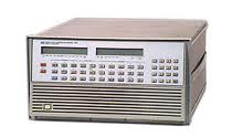
The HP3852A is probably one of the least understood vintage HP items you can buy on eBay. It was once sold as a "measurement mainframe" and that is exactly what it is. It is. Ie a mainframe with a PSU, a CPU and slots for modules. A HP3852 does not do much on its own, but if you stuff it with various cards, then it becomes a quite versatile piece of kit.
It can even work completely on its own, boot from a disk drive and carry out automated measurement tasks, storing the results to disk. Back in the mid-eighties, buying a HP 3852A would have set you back $4350, which would be approx $10.000 in today's money. See this PDF for prices
Used units can be found on eBay starting at 100$. It might be worth while to check out the FW version by typing IDN? on the console. The latest (last) FW is 4.22. A more recent FW is needed for some cards. For upgrading the FW, see below.
Once you bougt one and have it in your hands, then the first thing will be to replace the battery, unless the previous owner has already done so. A leaking battery will destroy the cpu board beyound repair. To replace the battery, follow the same disassembly instructions as for the ROM upgrade.
This is a fairy complete list of available cards
| Module | Description | Min ROM |
| 44701A | Integrating VM | 1.0 |
| 44702A/B | Hi-speed VM | 1.0 |
| 44704A | 16-bit HS VM | 4.2 |
| 44705A/H | 20-Channel Mux | 1.0 |
| 44705F | 20-Channel Mux | 1.0 |
| 44706A | 60-Channel Mux | 1.0 |
| 44708A/ | H 20-Channel Tcpl Mux | 1.0 |
| 44708F | 20-Channel Tcpl Mux | 1.0 |
| 44709A | 20-Channel FET Mux | 1.0 |
| 44710A | 20-Channel Tcpl FET Mux | 1.0 |
| 44711A | 24-Channel HS FET Mux | 1.0 |
| 44711B | 24-Channel HS FET Mux | 1.0 |
| 44712A | 48-Channel HS FET Mux | 1.0 |
| 44713A | 24-Channel HS FET Mux | 1.0 |
| 44713B | 24-Channel HS FET Mux | 1.0 |
| 44714A | Stepper Motor Controller | 3.0 |
| 44715A | Counter/Totalizer | 1.0 |
| 44717A | Static Strain Gage Mux | 2.0 |
| 44718A | Static Strain Gage Mux | 2.0 |
| 44719A | Static Strain Gage FET Mux | 2.0 |
| 44720A | Static Strain Gage FET Mux | 2.0 |
| 44721A | 16-Channel Digital I/O | 1.0 |
| 44722A | 8-Channel Digital I/O | 1.0 |
| 44723A | Digital Sense Control | 3.0 |
| 44724A | 16-Channel Digital I/O | 1.0 |
| 44725A | 16-Channel Gen Purpose | 1.0 |
| 44726A | 2-Channel Arb Wvfrm DAC | 3.5 |
| 44727A/ | B/C 4-Channel DAC | 1.0 |
| 44728A | 8-Channel Relay Actuator | 1.0 |
| 44729A | 8-Channel Power Controlle | 1.0 |
| 44730A | Track and Hold | 3.5 |
| 44732A | Dynamic Strain Gage FET Mux | 3.5 |
| 44733A | Dynamic Strain Gage Fet Mux | 3.5 |
| 44736A | Breadboard | 1.0 |
| 44736A | H05 LVDT Module | 4.2 |
| 44788A | HP-IB Controller | 3.5 |
| 44789A | Serial Interface | 4.0 |
| 44790A | Binary Mode Software | 3.6 |
The HP 3852A is programmed in a subset of HP BASIC. I have collected a number of useful programs below, to save you from typing.
Assuming a 44701 voltmeter in slot 6 and a 44711 FET multiplexer in slot 5. Take one reading from each of the 24 inputs and print over GIPB.
USE 600;
SCANMODE ON;
CONFMEAS DCV,500-523;
Assuming a 44701 voltmeter in slot 6. Take ten readings from the external input and print over GIPB.
OUTBUF ON;
USE 600;
RST 600;
TERM EXT;
NRDGS 10;
AZERO ONCE;
TRIG INT;
XRDGS 600,10;
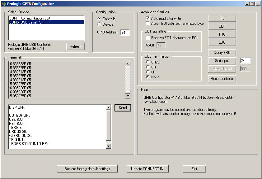
Assuming a 44701 voltmeter in slot 6. Take twenty readings from the external input and store in a variable, then print.
DISP OFF;
REAL RP(100);
OUTBUF ON;
USE 600;
RST 600;
TERM EXT;
NRDGS 20;
AZERO ONCE;
TRIG INT;
XRDGS 600,20 INTO RP;
VREAD RP;
Assuming a 44788 GPIB in slot 2 and a disk drive attached to it as 0. open a file called "EXAMPLE". Write a string, an integer and a real. Then close the file.
CREATE BDAT 'EXAMPLE',7,128;
ASSIGN @PATH1 TO 'EXAMPLE';
OUTPUT @PATH1 'FIRST',24,2.6;
ASSIGN @PATH1 TO *
Assuming a 44788 GPIB in slot 2 and a GPIB printer attached to it as 7. Print a string on printer
PRINTER IS 207;
PRINT "Hello World!";
Assuming a 44788 GPIB in slot 2 and a disk as 0. Open a text file, take one measurement on three channels and log to disk. For some reason you cannot dump an entire REAL array into an ASCII file, the way you can with a BDAT file. See the example below.
INBUF ON;
REAL RP(10);
CREATE ASCII 'DATA11',7;
ASSIGN @PATH1 TO 'DATA11';
USE 600;
SCANMODE ON;
CONFMEAS DCV,500-502 INTO RP;
OUTPUT @PATH1 RP(0);
OUTPUT @PATH1 RP(1);
OUTPUT @PATH1 RP(2);
ASSIGN @PATH1 TO *;
Assuming a 44788 GPIB in slot 2 and a disk as 0. Open a data file, take 10 measurements at one minute intervals for an hour and log to disk.
INBUF ON;
REAL R;
REAL RP(10);
CREATE BDAT 'DATA4',7,128;
ASSIGN @PATH1 TO 'DATA4';
USE 600;
SCANMODE ON;
SUB M7;
FOR R = 0 TO 60;
TIMEDATE;
CONFMEAS DCV,500-509 INTO RP;
OUTPUT @PATH1 RP;
INDEX RP 0;
WAIT 60;
NEXT R;
SUBEND;
CALL M7;
ASSIGN @PATH1 TO *;
Finding actual SS/80 or CS/80 disks can be a challenge. A simple solution is to use an SD-card based "disk" like my HPDisk or a PC-based one, such as Ansgar's HPDrive
To use the data on your PC, simply extract it, using HPDir, ie hpdir -extract imagefile DATA11. This will extract a file called DATA11.ASCII with the measurement data.
The 44726A DAC is a really neat module. It has two independent DACs and creates output from a waveform memory. This can be populated with data for standard waveforms, such as Sine or square, or with completely arbitrary data to create an arbitrary waveform. You can also use the High Speed voltmeter, to sample a real waveform, store it and then output a copy through the DAC.
Assuming a 44726A DAC in slot 1. Output a damped Sinewave
RST;
WAIT 1;
REAL e,a,w;
e=2.71828;
a=4/1000;
w=(2*PI)/50;
SUB LOAD_ARY;
  INTEGER T;
  REAL WV_AMP(999);
  FOR T=0 TO 999;
    VREAD e^(-a*T)*SIN(w*T) INTO WV_AMP;
  NEXT T;
SUBEND;
CALL LOAD_ARY;
USE 100;
WFWRITE ARB 1 WV_AMP TBASE (1/(800*1E3));
FILTER ON;
APPLY WFV 100, 1;
TRIG INT;
TARM AUTO;
Assuming a 44726A DAC in slot 1. Output an increasing Sinewave
RST;
WAIT 1;
REAL e,a,w;
e=2.71828;
a=4/1000;
w=(2*PI)/50;
SUB LOAD_ARY;
  INTEGER T;
  REAL WV_AMP(999);
  FOR T=999 TO 0 STEP -1;
    VREAD e^(-a*T)*SIN(w*T) INTO WV_AMP;
  NEXT T;
SUBEND;
CALL LOAD_ARY;
USE 100;
WFWRITE ARB 2 WV_AMP TBASE (1/(800*1E3));
FILTER ON;
APPLY WFV 100, 2;
TRIG INT;
TARM AUTO;
Assuming a 44726A DAC in slot 1. Linear steps, staircase. Using integers Sync pulse at start of every cycle
RST;
WAIT 1;
SUB LOAD_ARY;
INTEGER AMP_ARAY(10),I;
FOR I=0 TO 10;
  VWRITE AMP_ARAY I;
NEXT I;
SUBEND;
CALL LOAD_ARY;
USE 100;
WFWRITE ARB 3 AMP_ARAY TBASE (1/(11*1E3));
APPLY WFV 100 3;
SYNC WF;
TRIG INT;
TARM AUTO;
Assuming a 44726A DAC in slot 1. Linear steps, staircase. Using reals. Sync pulse at start of every cycle
RST;
WAIT 1;
SUB LOAD_ARY;
REAL AMP_ARAY(20),I;
FOR I=0 TO 10 STEP .5;
  VWRITE AMP_ARAY I;
NEXT I;
SUBEND;
CALL LOAD_ARY;
USE 100;
WFWRITE ARB 3 AMP_ARAY TBASE (1/(11*1E3));
APPLY WFV 100 3;
SYNC WF;
TRIG INT;
TARM AUTO;
Assuming a 44726A DAC in slot 1. Quadratic ramp. Sync pulse at start of every cycle
RST;
WAIT 1;
SUB LOAD_ARY;
REAL AMP_ARAY(20),I,J;
FOR I=0 TO 3 STEP .15;
  J=I*I;
  VWRITE AMP_ARAY J;
NEXT I;
SUBEND;
CALL LOAD_ARY;
USE 100;
WFWRITE ARB 3 AMP_ARAY TBASE (1/(11*1E3));
APPLY WFV 100 3;
SYNC WF;
TRIG INT;
TARM AUTO;
Assuming a 44726A DAC in slot 1. // Square Wave Pulse
RST;
WAIT 1;
USE 100;
WFWRITE SQV 5 5.0 OFFSET 2.5 TBASE (1/(4*100E3));
APPLY WFV 100 5;
TRIG INT;
TARM AUTO;
Assuming a 44726A DAC in slot 1. 1kHZ to 4kHZ Swept sinewave
RST;
WAIT 1;
USE 100;
WFWRITE ACV 6 10 PTS 200 TBASE (1/(200*1E3));
FILTER ON;
APPLY WFV 100 6;
TRIG INT;
TARM AUTO;
SUB SWEEP;
REAL I;
WHILE 1;
  FOR I=5E-6 to 1.25E-6 STEP -.25E-6;
  WAIT 0.1;
  TBASE I;
  NEXT I;
END WHILE;
SUBEND;
CALL SWEEP;
Assuming a 44726A DAC in slot 1. Illustrates an arbitrary waveform with individual sample lengths (in T_INTS)
RST;
WAIT 1;
REAL WV_AMP(9);
INTEGER T_INTS(9);
VWRITE WV_AMP 3,5,3,1,1,3,5,3,1,1;
VWRITE T_INTS 0,0,0,2,0,0,0,0,2,0;
USE 100;
WFWRITE ARB 8 WV_AMP NPER T_INTS TBASE (1/(100*16));
APPLY WFV 100 8;
TRIG INT;
TARM AUTO;
Something for the Audio buffs out there. This program generates a sine that is stepped exponentially from 7Hz to 20kHz. For each step, a reading is taken on the high speed voltmeter. Since the voltmeter only does DC, you need to use a rectifier or true-RMS converter to transform the wave to DC. Then just attach an amplifier or filter between DAC and voltmeter and you will get a list of frequency/voltage pairs that can be made into a graph.
// 7HZ to 22kHZ Sweep, sampled on every frequency
RST;
DISP ON;
OUTBUF ON;
REAL R;
WAIT 1;
USE 100;
WFWRITE ACV 6 10 PTS 40 TBASE (1/(200*1E3));
FILTER ON;
APPLY WFV 100 6;
TRIG INT;
TARM AUTO;
SUB SWEEP;
REAL I;
WHILE 1;
  FOR I=5 to 13.5 STEP 0.5;
  USE 100;
  WAIT 1;
  TBASE (1/EXP(I));
  USE 600;
  RST 600;
  TERM EXT;
  NRDGS 1;
  AZERO ONCE;
  TRIG INT;
  XRDGS 600,1 INTO R;
  VREAD EXP(I);
  VREAD R;
  NEXT I;
END WHILE;
SUBEND;
CALL SWEEP;
For simple testing, you will find the KE5FX toolkit invaluable.
John Miles has graciously given me permission to host a modified copy of his prologix.exe utility. I have added some tweaks to make working with the HP 3852A easier. The modified version allows you to paste in a whole block of text and then send it, line by line, with a electable inter-line delay. You can also specify a comment-sequence and all characters after that sequence will be dropped. Ie Specify "//" and then send:
PRINTER IS 207 // 44788 card in slot 2, printer address 7;
PRINT "Hello World!";
Will send the following to the instrument. The inter-line delay is nice for testing. It allows you to read the errors on the 3852A display before they file up.
PRINTER IS 207
PRINT "Hello World!";
Useful GPIB Information
A Tutorial Description of the HPIB Bus
GPIB / IEEE 488 Basics Tutorial
The GPIB FAQ
Someone alerted me to these to videos that cover the HP 3852A. The first video goes through what the HP 3852A is and presents some of the plugin cards. The second one is a short introduction to programming the unit.
IE Blog HP 3852A Introduction Part 1
IE Blog HP 3852A Introduction Part 2
As noted earlier, the latest (4.22) firmware is required for some modules. If your unit is old then you might want to upgrade. The 3852A firmware resides in 6 or 8 27256 EPROMS or 27256 OTP (One Time Programmable) proms. The official upgrade kit has a part number of 03852-88739 and bears the HP/Agilent mark of quality. It includes not only the ROMs, but a detailed guide, a disposable wrist grounding strap and even a small piece of wire as some motherboards require soldering.
In case you cannot get your hands on the official kit, then you can find the instructions here and here. Note that I have linked to the HP Agilent group as I made a mistake reading the ROM images.
This information and the circuits are provided as is without any express or implied warranties. While every effort has been taken to ensure the accuracy of the information contained in this text, the authors/maintainers/contributors assume no responsibility for errors or omissions, or for damages resulting from the use of the information contained herein. I disclaim everything. The contents of the articles below might be totally inaccurate, inappropriate, or misguided. There is no guarantee as to the suitability of said circuits and information for any purpose whatsoever other than as a self-training aid. I.E. If it blows your equipments, trashes your hard disc, wipes your backup, burns your building down or just plain don't work, IT ISN'T MY FAULT. In the event of judicial ruling to the contrary, any liability shall be limited to the sum charged on you by us for the aforementioned document or nothing, whichever is the lower. I will not be held responsible for any damages or costs which might occur as a result of my advice or designs. Nor are you allowed to use any of my designs for commercial purposes without my written authorisation.
