20A Unipolar stepper driver - Assembly and testing
|
20A Unipolar stepper driver - Assembly and testing |
|
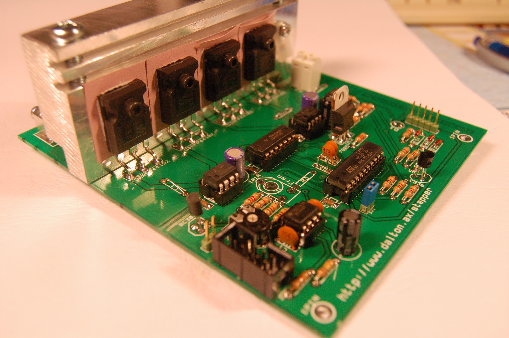
First solder the SMD capacitors. Use a magnifying glass and a steady hand and a fine-tipped iron. Then solder the rest of the passive components and the sockets, pinheaders etc. Then solder the 7805 regulator, making sure it goes in the right way. Solder the NTC resistor so that it makes (thermal) contact with the cooling fin (see the pictures). Do not socket the ICs, yet.
Note that you need either four or eight power resistors to make up Rs, depending on max current. They should be low-inductance. Mount them slightly raised (say 1mm) over the board to ensure adequate cooling.
Mount either screw terminals (Keystone KEY-7690 or 8197) or blade terminals for the motor connections.
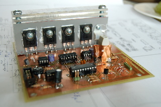
Bend the legs of the power mosfets carefully, using pliers to protect the plastic housing so that the legs fit in the holes when the mosfet and cooling fin holes are aligned. The extra bend is to take up any thermal flexing. Smear a very thin layer of silicone grease on the mosfet, then put the Keratherm insulator on top and smear another very thin layer on top. Fasten the transistors using insex M3 screws and belleville washers. Tighten to approx 0.7Nm. An insex key and a fish scale works in the absence of a real torque wrench. Measure the length of the key and do the maths.
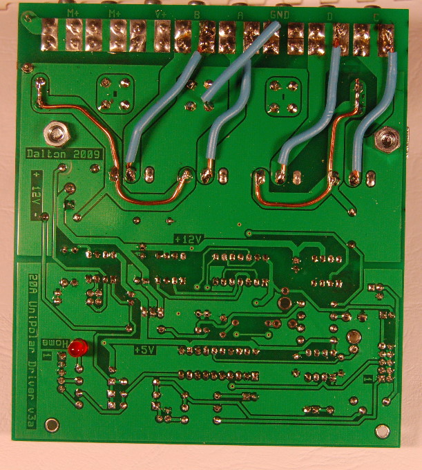
If you intend to run this driver at 5 amps or above, then solder heavy wires over the critical paths as can be seen in the picture below.
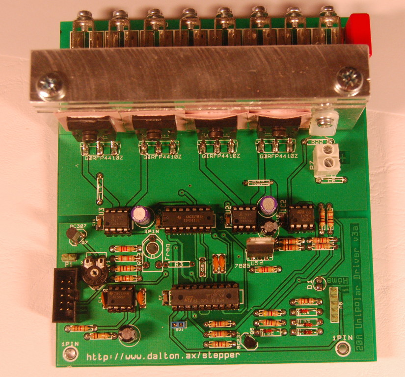
The driver can be run with the built-in L276 RC oscillator in which case you need RV2, R3 and C3. You can also (recommended) run the oscillator on one and sync the rest with this. See the L297 datasheet for more info. Alternatively you do as I do and use an external oscillator. In that case you omit RV2, R3 and solder a link over C3. External clock is then fed to pin 1 of P8.
Inspect the board carefully for bad solder joints and possible solder bridges.
Before installing the ICs, apply 12V to P7, observing polarity. Then use a voltmeter to verify +5V on pin 8 of U4 and IC2. Pin 14 of U1 and 12 of IC1. Pin 6 of U2 and U3 should have +12V. If the board passes this test, then disconnect and insert the ICs and connect everything but the motor power. Apply power and the home LED should light up.
Before connecting the motor and applying motor power, I strongly suggest testing the board as follows: Using 12V for motor power and suitable automobile lamps, say 12V 20W. Connect the lamps between M+ and A,B,C and D. Turn on and apply motor power and step. The lamps should now light up in sequence.
Adjust Vref for correct Imax. With the controller stepping, Measure on the wiper of RV1 or pin 15 of IC1 adjust until you have the voltage that corresponds to your desired Imax. Ohms law applied, ie if Rs is 0.04 ohms (2x0.02) and you want 10A, then the voltage should be 10 x 0.02 = 400mV. Stop stepping and verify that Vref drops to approx half after 10 seconds when U4 times out.
The board should now be ready for operation. Good luck!
