20A Unipolar stepper driver
|
20A Unipolar stepper driver |
|
This page describes the design of an Unipolar Stepper Motor driver, able to handle up to 20A. The goal was to create an inexpensive driver for old stepper motors.
The answer is: "It depends". The limiting factor is avalanche energy. This energy (Ear) is proportional to the winding inductance and the square of the current. Just make sure that you do the maths and take care of the generated heat (see below) and you should be fine. I have run the prototype at 20A, but settled for 10A for these motors as it was enough fot the torque needed.
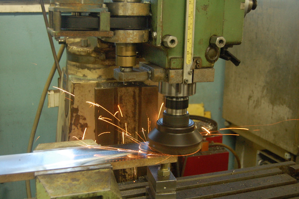
The project arose from a need to computerise a rather ancient Beaver Mill, not unlike the one seen on the pictures in this link. The mill had been used by a company that produced precision gear for the industry, retired and put in a barn for storage. Unfortunately had the local colony of rats taken a liking to the control-cabinet, judging by the smell, to use as a latrine. The electronics was possibly still functional, but not in a condition where you wanted to touch it. The decision was made to use the mechanics and the steppers. The steppers are 1.6V 20A 200steps/rev Slo-Syn steppers. Incredibly sturdy pieces of work that were rated at 7.8Nm, but would easily pull over 9Nm even at 15A current. (Measured by lifting weights on a string over a pulley).
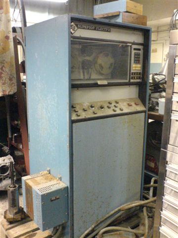
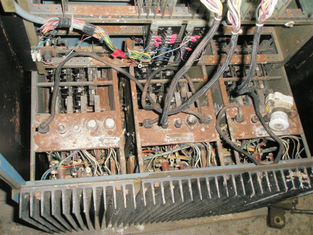
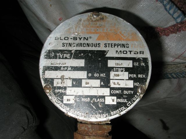
The motors are Slo-Syn with 200 steps per revolution , 1100 oz.in. , 1.3v. 20A , type M113-FJ40. Like so many of their contemporaries they were unipolar (six-wire) and were originally driven by a 120V LR-drive. Since no suitable drivers were found we embarked on designing our own. The old drivers were scrapped, except for the cooling fins, sized like a football field, which were reused.
| Motor data Sheet - MOTOR_TYPE M113-FJ40 | |
| AC/DC | DC |
| DC Holding Torque | 1550 |
| Steps/ rev | 200 |
| VOLTAGE | 1.240 |
| Current | 20.000 |
| Phase Resistance | .062 |
| Phase Inductance | .66 |
| Termination | 6 TERM |
| Front Shaft length | 1.380 (35.052mm) FSHAFD 0.625 |
So much has been written on stepper motors, both in print and on the web, so I see no point in repeating it all. The possibly best text is the one by Douglas W Jones, found here: Jones on Stepping Motors. If you are new to steppers, then I suggest you take the time to read through his material and then return here.
To put it short: Current gives the torque, voltage the speed. The trick is to get the voltage into the windings fast enough for the current to rise. The higher the initial voltage, whilst limiting the current, the faster the stepper can turn (up to a limit). At the same time does raising the voltage create challenges, so in the end, the result is always a compromise.
We decided to use an Unipolar,. Chopper driver that in our opinion offers the best compromise between performance and cost. A good explanation of a chopper driver can be found in the paper mentioned above and also here
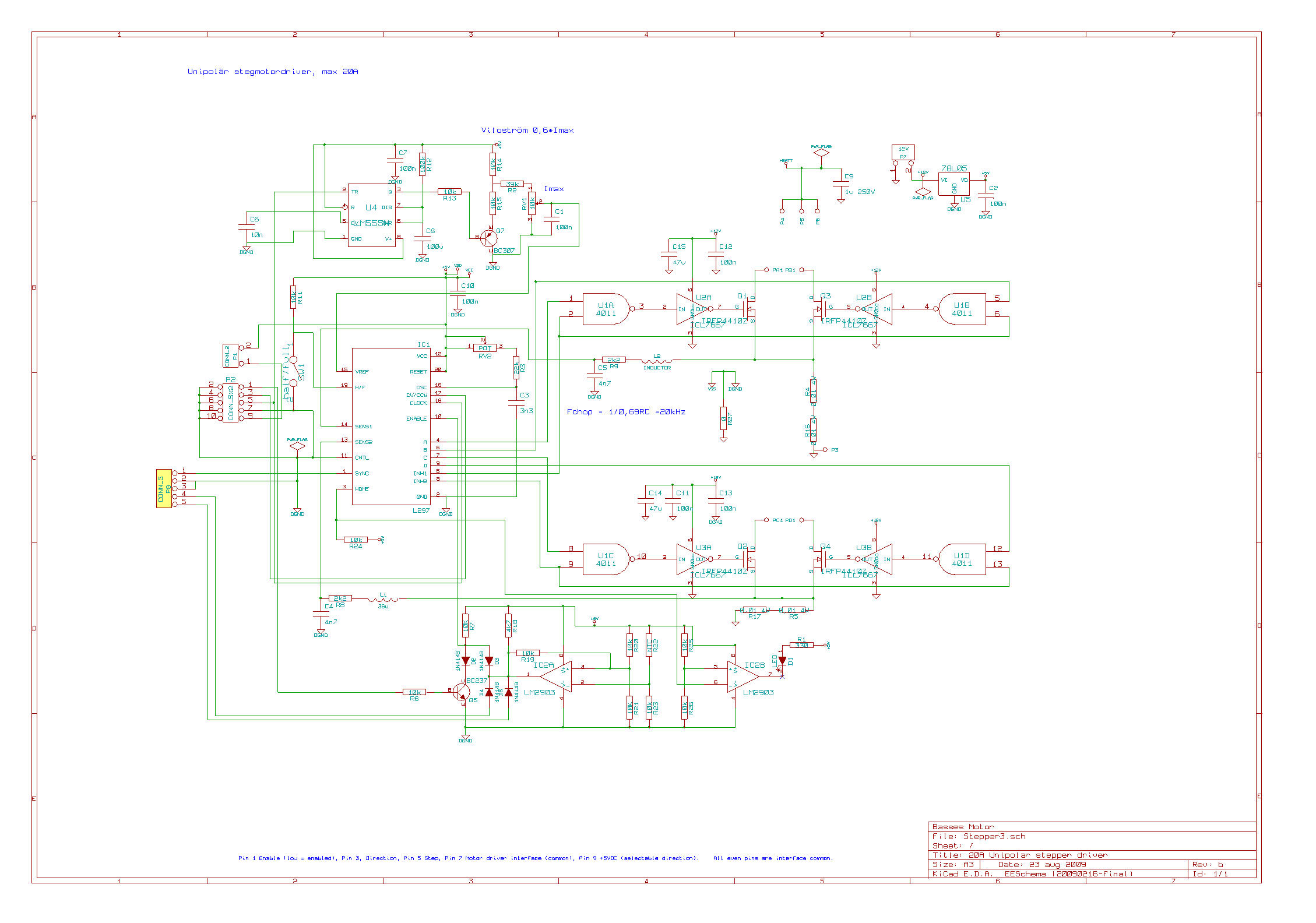
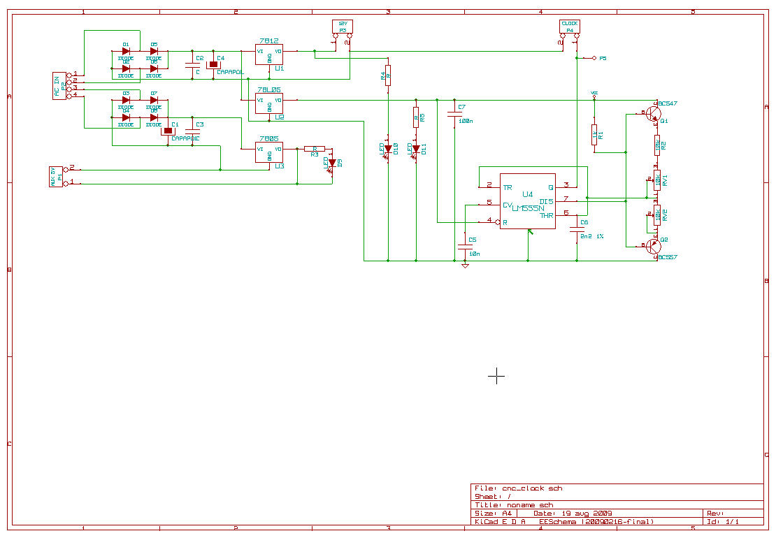
We based the driver on the popular L297 driver IC. Mainly because it is widely available and also very well documented. The driver circuit is more or less taken from the L297 datasheet.
Many example driver circuits found floating around the web are geared towards small, toy motors. When you end up switching 20A into an inductor then tiny things like design and layout really matters.
One common problem with chopper drivers is motor noise. You try to locate the chopper frequency above the audible spectrum, say 18..22kHz, but often does the driver decide to use a fundamental of this frequency, humming along (or rather squealing along) at 10kHz or 5kHz. The issue is described here: http://www.st.com/stonline/products/literature/an/1675.pdf To combat this we essentially did three things:
One big reason for not using unipolars is because you have little or no control over current decay. To get reasonable speed out of the motor, you need to have the magnetic field collapse asap when you turn off the winding. Adding snubber diodes to the FETs will seriously hamper this decay so that is not an option. Several esoteric methods are discussed here For more on current decay, see this appnote from TI.
In the end, a simpler solution exists; Power mosfets contain an integral body diode. Modern FETs has this diode tweaked to that it acts like a zener. Voltage is allowed to build up, until you get avalanche breakdown in the fet. This breakdown is non-destructive, as long as you do not exceed the maximum ratings of the FETs (see AN10273_1.pdf from NXP). The chosen FET, IRFP4410 has a maximum, repetitive Ear of 50mJ at 90 degrees ambient. Breakdown voltage is typically 120V. When you turn off one winding, the kickback is dissipated in the diode, as can be seen in the pictures below. Left is actual and right is a simulation in LTSpice.(Red=Winding current, Green=Vd). The simulation model can be found here.
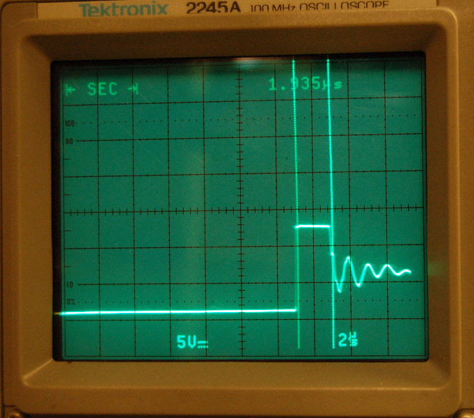
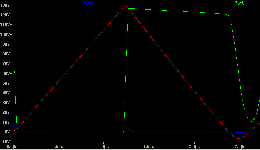
The voltage rises to the avalanche point and stays there for 1us. The actual time and thus energy depends on the current and the voltage. The energy, Ear is 120V * 10A * 2us / 2 = 1.2mJ Certainly, one issue to watch out for is heat. Even if the FETs are rated at 97A continous, we will quickly reach a point where avalance losses create enough heat to destroy the FET. The limit is probably 75W per transistor, assuming a large heatsink and possibly forced cooling. (75W/20kHz = 3.75mJ)
For a more thorough discussion on avalanche design, please turn to AN2344 and AN-1005
The issue here is to get the heat out of the FET. IRFP4410Z has a RthJC Junction-to-Case 0.65 °C/W and RthCS Case-to-Sink, Flat Greased Surface 0.24 °C/W. A silicone pad adds another 0.4 °C/W for a total of 1.29 °C/W. 75W will give a temperature gradient of 97 °C between die and cooling fin which means you need to keep the cooling fin below 78 °C. In reality we want to be well below that to be on the safe side. One way is to select an IRFPS3810PbF wich has similar electrical data, but comes in a Super-247 package with RthJC Junction-to-Case 0.26 RthCS Case-to-Sink, Flat, Greased Surface 0.24 °C/W. The total, junction to sink is then 0.9 °C/W instead of 1.29 °C/W which equates to a 30°C lower temperature.
Replacing the silicone insulator (0.4 °C/W) with Kertaherm Red (0.07 °C/W) gives a further 25°C reduction in temperature.
I also recommend reading and following the guidelines in AN-1040 - Mounting Considerations for Power Semiconductors if you intend to run this driver close to its limits.
L297 plus 4011 is more or less taken from the L297 appnotes. Note that I have reserved space for chokes as well in the Vsense lines. If used, they should be small, ie a link with a ferrite bead. I have also reserved space for using the on-board clock, but when using an external one, simply omit RV2 and R3 and substitute a link for C3. The external clock is then fed to P8.
U4 is a monostable with a time-constant of approx 10s. It is triggered by the incoming pulses so the output is normally high and Q7 off. After 10s of inactivity, output goes low and Q7 starts to conduct, lowering Vref by approximately 60%. This is to keep driver and motors cooler.
IC2A is a simple thermostat. R22 is mounted on the heatsink and when the temperature rises above 65C the comparator will flip, pulling the L297 enable line low. It will also signal ESTOP to the CNC software (through pin 4 of P8) and to an indicator light, common to all three drivers. Purists may say that the three resistors should be metal-film, but at the end of the day if you get resistors from the same batch, then they are probably matched enough. Also the exact temperature is not that important, as long as the driver shuts down when it gets too hot. The temperature is set through R23. 22k is approx 65C, 19K is 70C etc.
IC2B is simply an inverter/driver for the home-indicator LED.
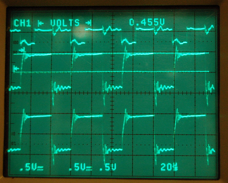
Voltage over Rsense with two windings active. Clock is onthe top for reference. Current is 0.455V/0.4ohm = 11A
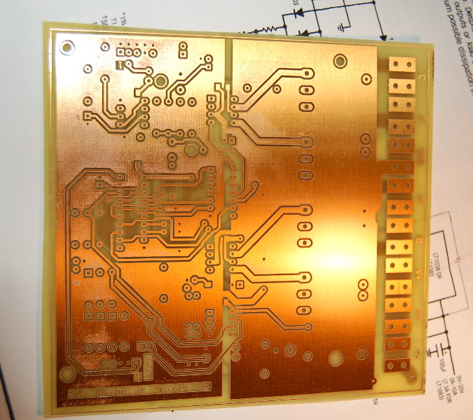
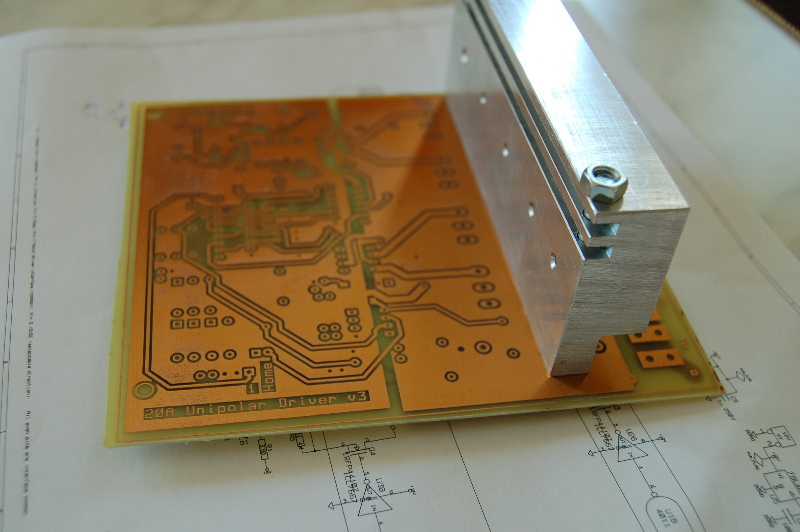
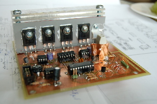
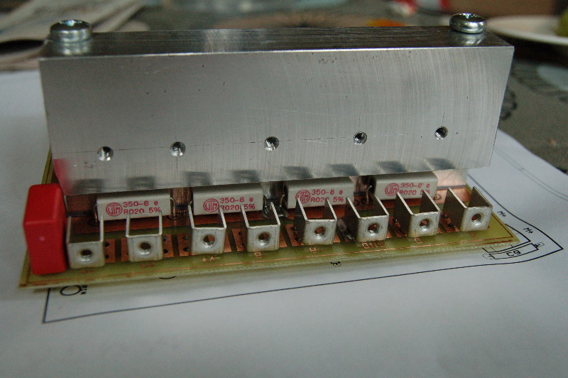
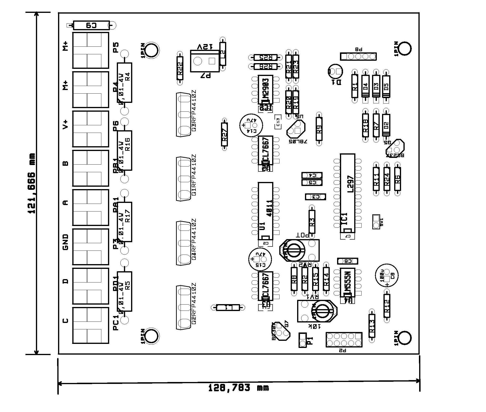
Stepper driver PCB. The large aluminium piece is bolted down on the main cooling fin.
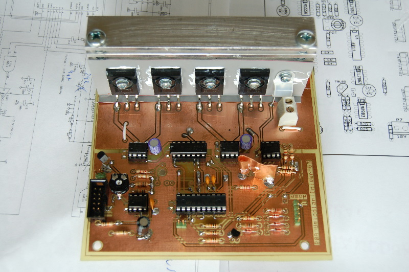
Finished board. The home led is soldered on the solder side of the PCB so that it is visible when the board is bolted to the fins.
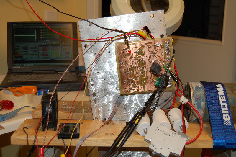
Running the motor at 10A, using a G-code program that simulates movement and milling with pauses. Cooling fin reached 40C after an hour.
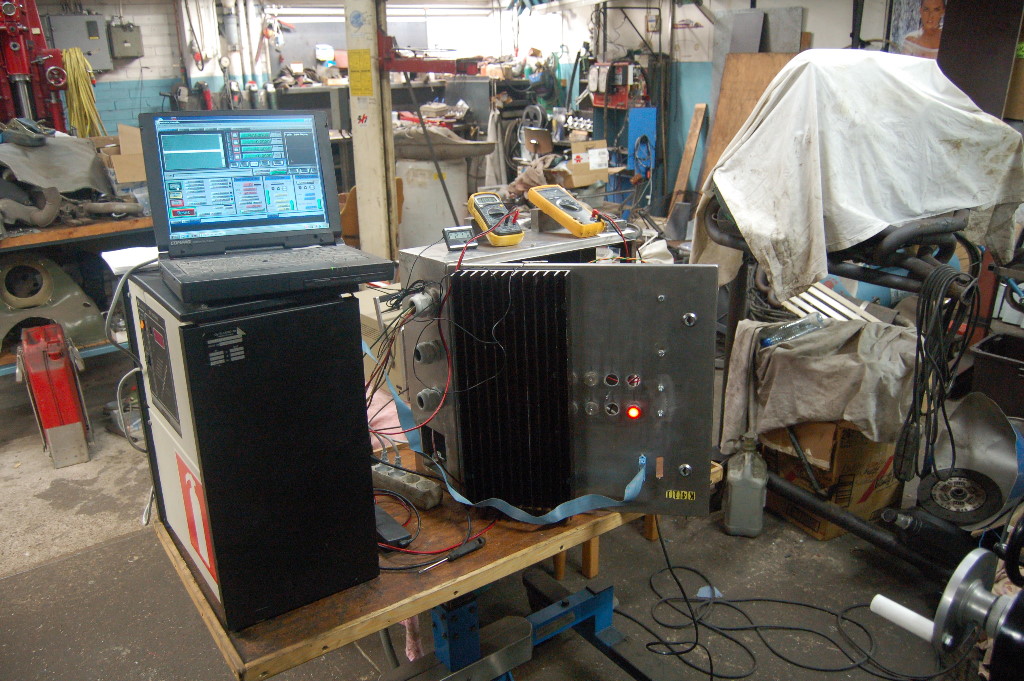
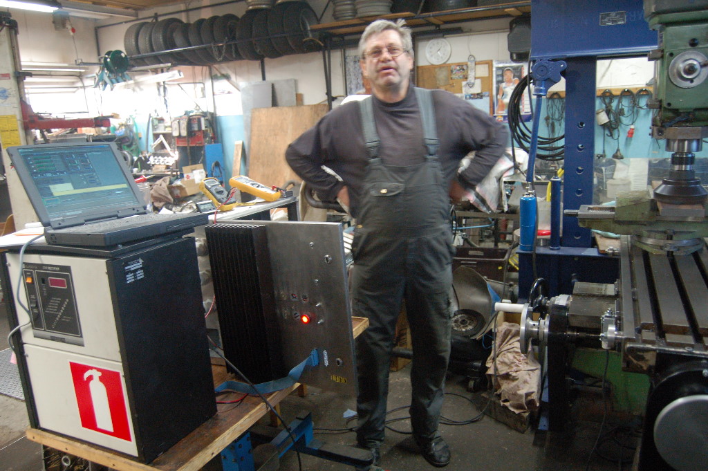
We built the driver for one axle and mounted all of the stuff in a nice stainless-steel cabinet in order to do some trial runs milling real steel. This was done to ascertain that the driver acted as we wanted in real life and to find out what motor current we needed for a reliable feed. This test used a motor voltage of 30V and a motor current of 10A. With this setting the motor was able to move the mill table 2000mm/min.
The PSU is an old 24V battery charger. Releived of its innards, short of the transformer, choke and thyristor bridge and with some new electronics, it is now capable of providing up to 75V at 25A or more. It is a scary piece of equipment of you happen to short it accidentally!
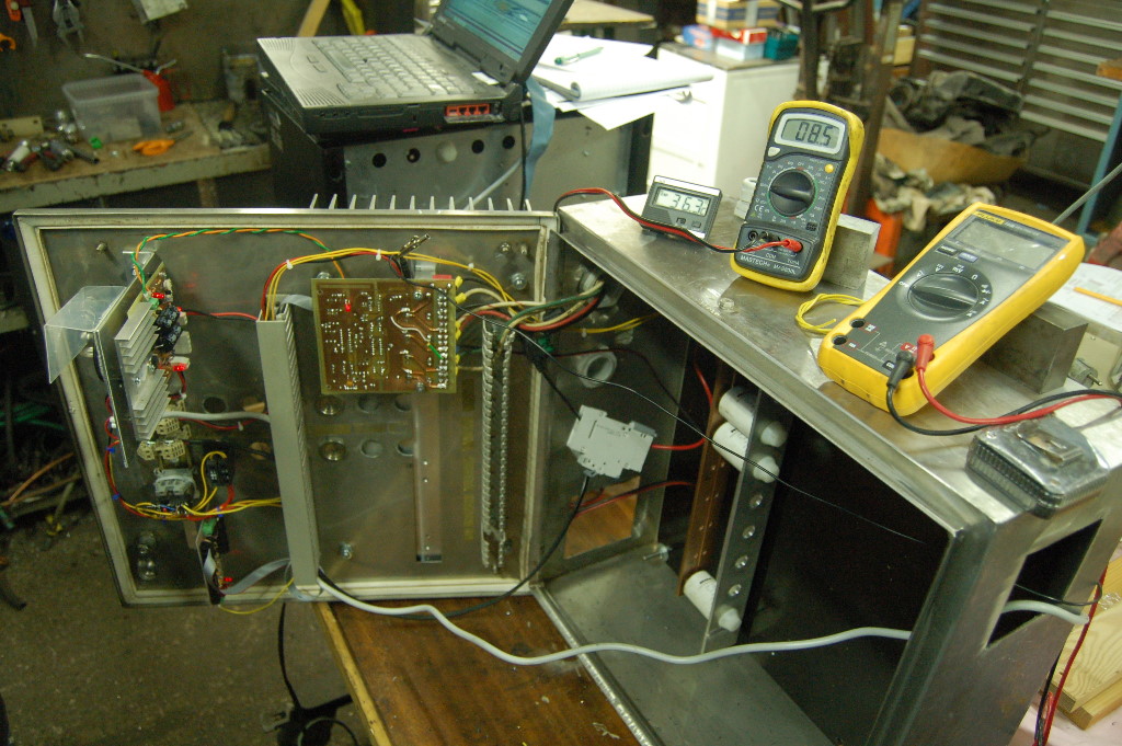
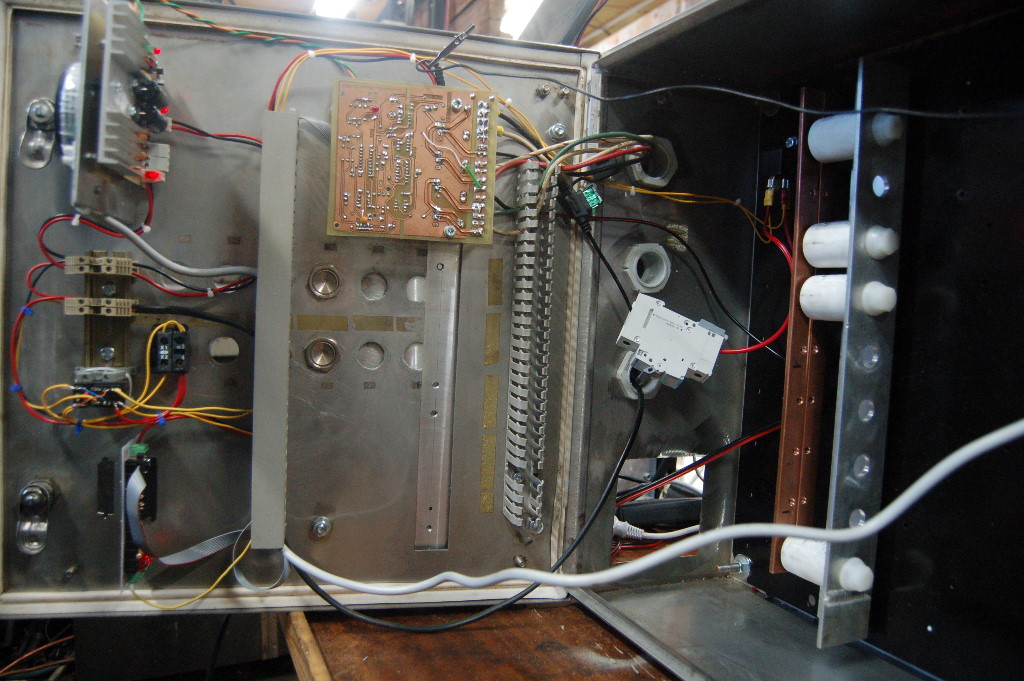
Stainless Steel cabinet innards. From the left we have the logic PSU that supplies 12V to the logic and a floating 5V for the breakout board. It also provides the clock for the three axle drivers. Below that we have the on switch and a small relay for the emergency and limit switches. Below that is the breakout board. To the right is the X-axis driver and space for Y and Z. A bank of four 4700u 63V capacitors are on the right as well as the relay for the motor voltage. The circuit breaker is a temporary solution, just for this test.
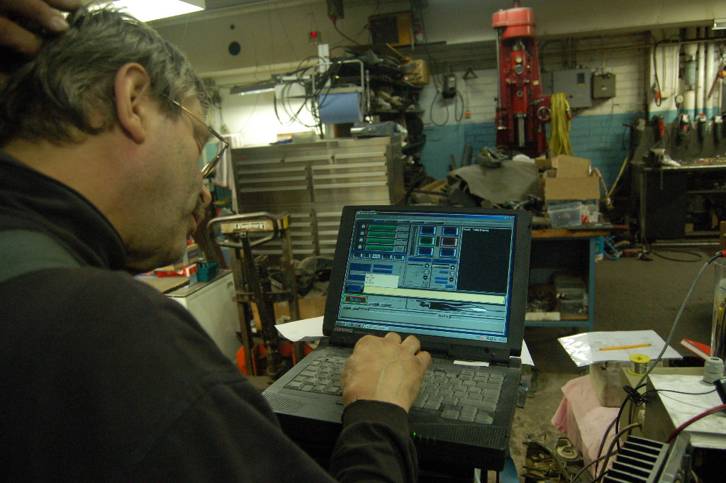
The small thermometer reads 36.3 degrees and the small multimeter reads 8.5 which is the voltage (mV) over the 2mohm shunt. Ie we are drawing 4.25A from the main supply. Now the real fun begins... trying to figure out Mach3...
All three drivers are now cooled by a fan that manages 2,40 m3/min of airflow. Cooling fin temperature is below 20C even when running the mill for several hours.
Stepper
Clock and logic power. Supplies 12V to the stepper logic and 5V isolated for the breakout board.
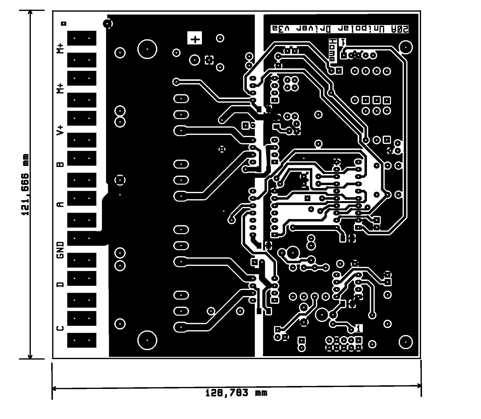
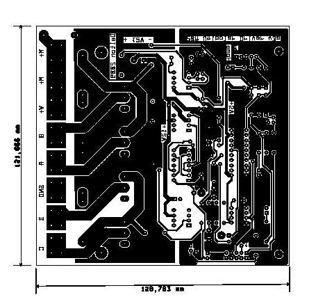
Note that the traces, even this wide, will not carry 20A on a 35u board.The easy solution is to solder 1 or 1.5mm wires on top of the wide traces.
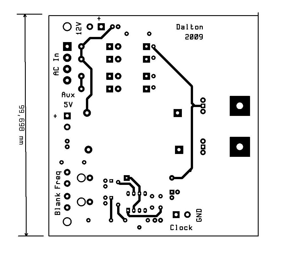
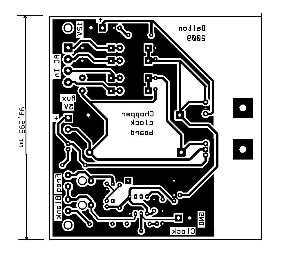
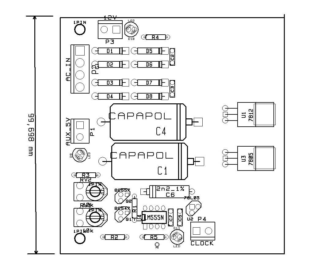
Master clock and 12/5V logic supply
This information and the circuits are provided as is without any express or implied warranties. While every effort has been taken to ensure the accuracy of the information contained in this text, the authors/maintainers/contributors assume no responsibility for errors or omissions, or for damages resulting from the use of the information contained herein. I disclaim everything. The contents of the articles below might be totally inaccurate, inappropriate, or misguided. There is no guarantee as to the suitability of said circuits and information for any purpose whatsoever other than as a self-training aid. I.E. If it blows your equipments, trashes your hard disc, wipes your backup, burns your building down or just plain don't work, IT ISN'T MY FAULT. In the event of judicial ruling to the contrary, any liability shall be limited to the sum charged on you by us for the aforementioned document or nothing, whichever is the lower. I will not be held responsible for any damages or costs which might occur as a result of my advice or designs. Nor are you allowed to use any of my designs for commercial purposes without my written authorisation.
