| GPIB disk emulator |
Please note that several components used in HPDisk have had extremely long delivery times recently. I was quoted several months for the humble BSS308. Bear this in mind when ordering boards and contact me for an updated BOM.
NEW: PIC18F47K42 support. Proper bootloader. Revised, but backwards compatible PCB - Read below for more info
NEW: NetBSD/300 v9.1 image - Read below for more info
NEW: New firmware version. HPDisk MKII - Read below for more info
We now have bare boards for sale. See below for details.
Pretty please! read the errata at the bottom of this page before assembling.
Fancy being able to store the data from your old HP163xx analyser? Or your Spectrum Analyzer? Or pretty much any old GPIB-instrument that supports a GPIB-Based disk? Or even that Old Commodore? Sounds Cool? Then this project is for you! Using a PIC 18F4620 an SD-card and a few other components, this project will emulate a HP 9121 disk drive, or other Amigo drives with minor changes in the code. The actual disk data is stored as an image file on the SD and should be readable by the standard Linux LIF utilities or the excellent HPDir utility. (Tested with version 2.03)
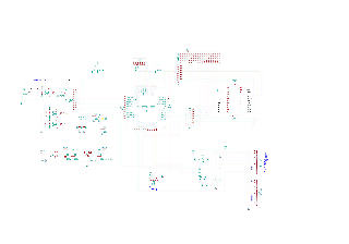
Clik on the schematic for a larger PDF
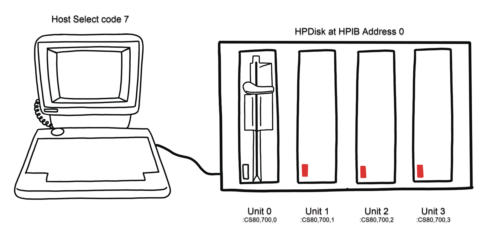
HPDisk is a disk emulator that emulates a HP disk, connected over GPIB (HPIB) and using the Amigo or CS/80 (or SS/80) protocol. The emulated disks are files on an SD-card. On the same card, formatted as FAT32, are one of two config files that determine several parameters for the drive itself and individual disks. The SD card can be read in an ordinary PC equipped with an SD-card reader or by using an SD to USB converter. The image below explains what it looks like to the host./p>
There are blank PCBs available. Occasionally do I have prebuilt units available. Contact me for specifics
The protocol used to control various types of disk drives over GPIB is sometimes called "Amigo" and sometimes "HP-300 Compatible HP-IB". It is fairly elegant and mostly compatible with IEEE-488. When I say mostly is because it implements an "ID" function that is not compatible with 488. The protocol has another weakness: The controller needs to have detailed knowledge of the drive, based on the "ID", ie drive geometry etc. Amigo was later superseeded by the CS/80 (Command Set for the 80's) and it's sister SS/80 (Subset 80) protocol that is more parameterised. Note that some HP units support Amigo, others CS/80, some support both. Check your manuals first! The current firmware supports Amigo and SS/80.
The problems with Amigo soon became evident. Each controller needed to have knowledge of each disk drive, so a new type could npt be used, unless you upgraded the firmware.
To overcome this, HP developed "Command Set for the 80's", later named CS/80 for typographical reasons. With CS/80, a controller needed only to issue a DESCRIBE and the
drive would return all the info the controller needed. Not only geometry, but also stuff like how much time a seek might take and so on. To boot, the protocol used a linear
addressing, instead of cylinder/head/sector. The maximum vector is 6-bytes, allowing a maximum disk size of 2^48 bytes, well beyond what was available in the 80's.
HP Also defined a subset of CS/80, called SS/80 to be used with low-cost drives.
The current firmware uses FATFs and us limited to 4Gb so you are limited to image files of max 4Gb. If you change the code somewhat and enable support for ExFAT in FATFs, then you could possibly have image files up to 2^48 bytes in size. Wheter that is useful for LIF disks is debatable, but could possibly be useful for HP-UX.
Both SS/80 and CS/80 have "proper" manuals, but Amigo was never formally documented as far as I know. The best Amigo documentation available today is probably the service manuals for old HP diskdrivers such as the HP 9895A and the HP 9123D, available from the HP Museum. Also see the very extensive documentation at The HPDrive Project .
One aspect that is indelibly woven into GPIB is the concept of polling. The controller need to be able to fire off a request to a unit, then go its merry way and return later and check for status. This check is called "polling" and GPIB defines two types: Serial and Parallell. With serial polling the controller addresses each instrument and asks for status. With many instruments, this can be slow. With parallell polling the controller gets the status of up to 8 units in one go. This is how a Parallell Poll takes place: The controller asserts (pulls low) ATN and EOI simultaneously. The units detect this and respond by pulling one dataline low to indicate completion. The actual address can be configured from the host, but the default is that the unit with address 0 pulls DIO8 low, address1 pulls DIO7 low, etc. As you can see, Parallell Polling has very little overhead, hence it is often used for disks.
The current firmware is hardcoded for address zero (0) so the jumper should be in the position marked 0 on the silkscreen. I decided to make it selectable in hardware in case I ever made the address configurable in software,
The design started out as a spinoff of my GPIB Adapter, but I had to change the PIC to a 44-pin part to have enough pins to control everything als also have room for expansion. I did some initial trials with the Microchip SD-library, but found it to be an overkill. Initially I ended up using PetitFATFS. PetitfatFS only supports one file and has some quirks when writing (you need to write a full sector of 512 bytes and you cannot create files), but takes up very little RAM. The current code, implementing a bare minimum of the Amigo protocol, weighs in at 15 250 bytes, leaving more than 50% of the RAM free for further expansion.
Note that the one file limit in PetitFatFs is not a problem. There is only one file on the SD-card and that file is an image of the LIF (HP) disk. All the LIF files you save from your instrument are inside this image file.
For the MKII version I now use the full FATFs version which means that I can have several open files. The current MKII FW supports up to 4 "disks" simultaneously. Ie it looks like say a HP9122 with 4 drives, numbered 0.3
The HP 9123D is a dual microfloppy drive with 70 tracks and 16 sectors/track. The protocol is Amigo. That drive is old enough so that it should be recognised by most old HP instruments. Data on the SD card is simply an image of the disk, starting with sector 0.
The HP 9122D is a dual microfloppy drive with 80 tracks and 16 sectors/track. The protocol is SS/80.
The HP 9134D is a Winchester (hard disk) with 303 tracks, 6 heads and 32 sectors/track. The protocol is SS/80.
HPDisk uses a flat file representation of a disk. Ie what you would get if you copied a disk to file using dd on Linux. The extension .BIN is just arbitrary, a binary file. A .HPI file can be used directly, but many disk images available on the internet are in other formats, say TeleDisk and need to be converted. This can be done with libdsk available on both Linux and Windows. TeleDisk images are usially have a .TD0 extension. To convert a disk image called BAS2SYS.TD0 to a .BIN file suitable for HPdisk, you use the command dskconv.exe" -otype raw BAS2SYS.TD0 BAS2SYS.BIN. I have been using libdsk 1.5.12 on Windows for testing.
The circuit is fairly straightforward. The 16 GPIB lines are connected to PIC ports and simply wiggled through the TRIS-bit. Ie the pin is made input to make it high/threestate and output and driven low to simulate the original GPIB open-collector drivers.
The SD-card operates at 3.3V so a separate regulator is needed for that. Using a 3.3V PIC is not an option because of GPIB signal levels. Level shifting between 5V and 3.3V is done with resistive dividers (5V->3.3V) and a mosfet (3.3V->5V). The circuit can be equipped with either a standard SD-holder or a micro one.
The circuit around U1 and Q1 might need some explanation: If we remember our Parallell Poll from above, then ideally, a device should respond within 100ns to a parallell poll (ATN and EOI asserted). To do this in software requires a silly high CPU speed. So this is better done in hardware. The parallel poll response is brought out on RA0, low for asserted and high for unasserted. If RA0 is low and both ATN and EOI happen to be low, then the output of the gate goes high Q1 turns on, pulling the selected dataline (through P8) low. Since the software default of this unit is address 0, you should pull DIO8 low. The purpose of P8 is to make the address selectable if need be in the future. For now, place the jumper in the topmost position, marked "0" on the PCB as the default address of the FW is 0.
I had some problems with the level shifter for the SD card. A good explanation of the problems can be found here, The fix is to change R4 to 1k8. I will also replace the FET with another one with lower Vth, such as BSH 103.
PCB can be equipped with either a standard SD-Card connector or a Micro SD one. Use an angled GPIB connector or a straight GPIB-plug with soldered on wires. Note that I have always used a male connector to allow the PCB to be plugged into an instrument. You need to watch out for the pin orientation. Pin 1 is the top left pin when seen from the component side and pin 24 is bottom right, grounded. A female PCB connector, such as Mouser 636-112-024-213R001 goes on the component side. A male PCB connector, such as 636-112-024-113R001 goes on the reverse side. Same for decoupling caps C7 and C8.
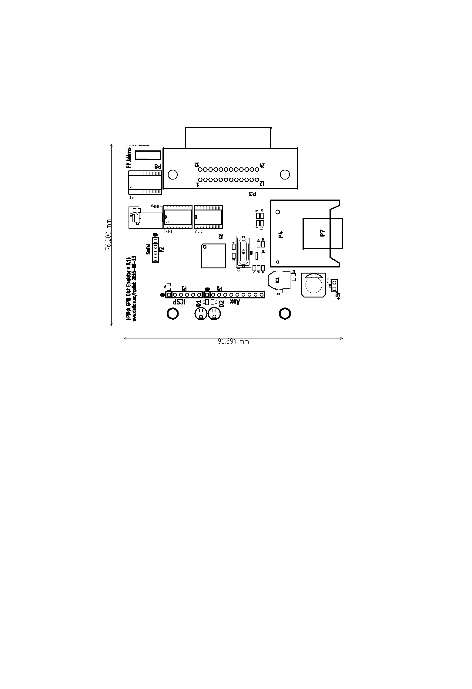
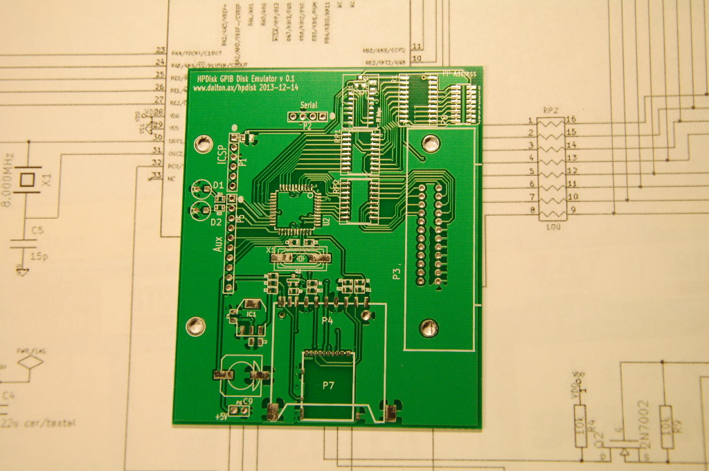
Bare PCB
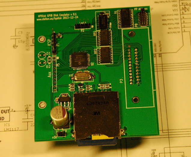
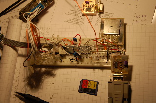
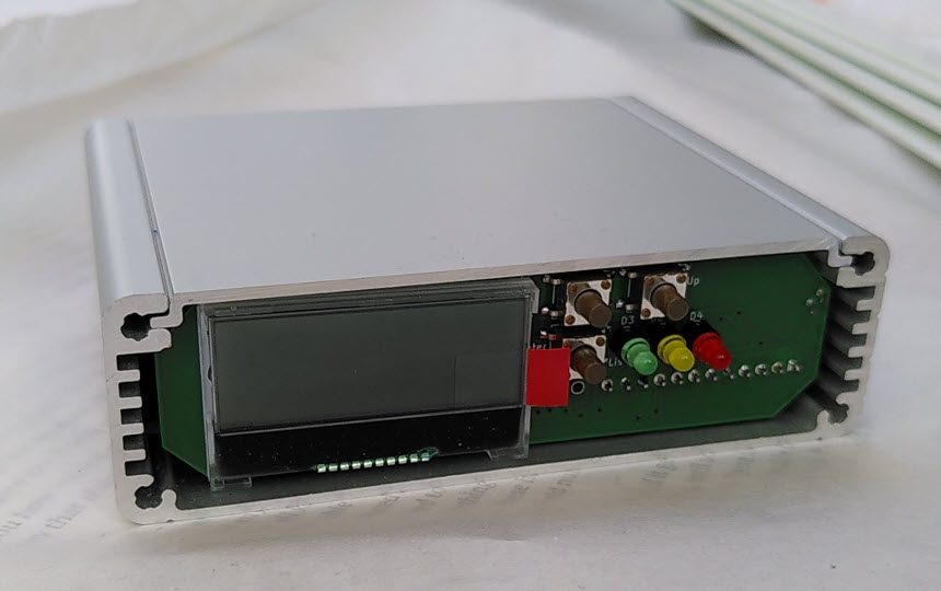
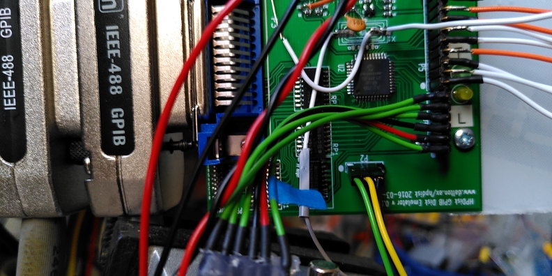
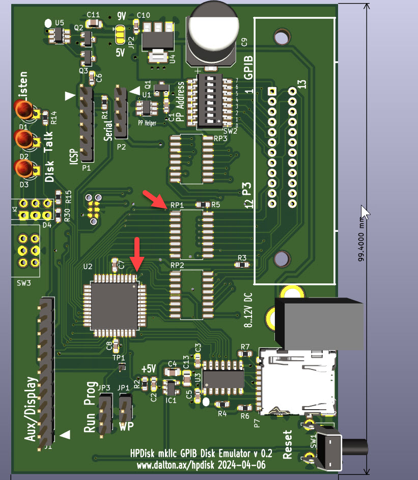
Populated PCB
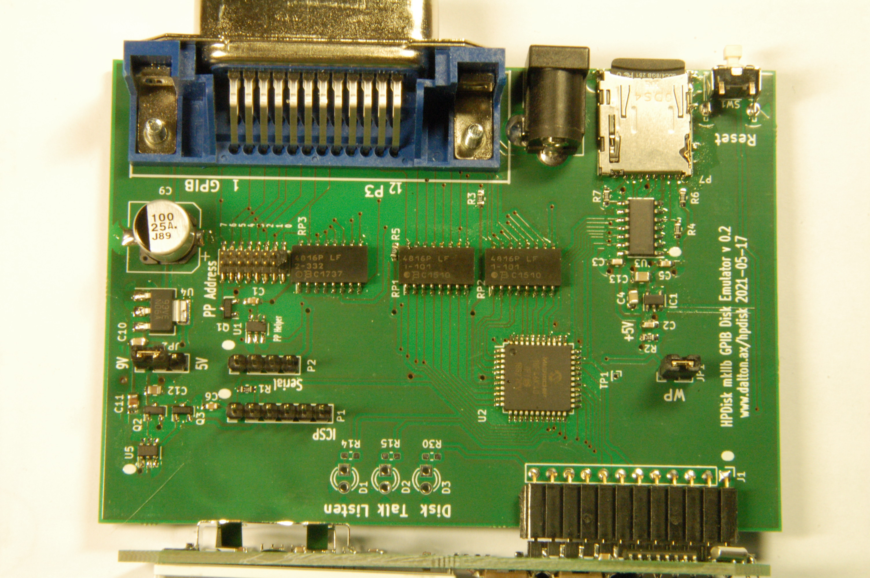
Populated MKIIb PCB
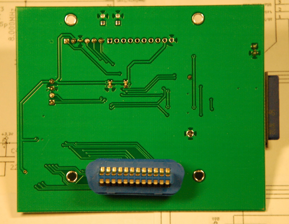
GPIB-connector on reverse side
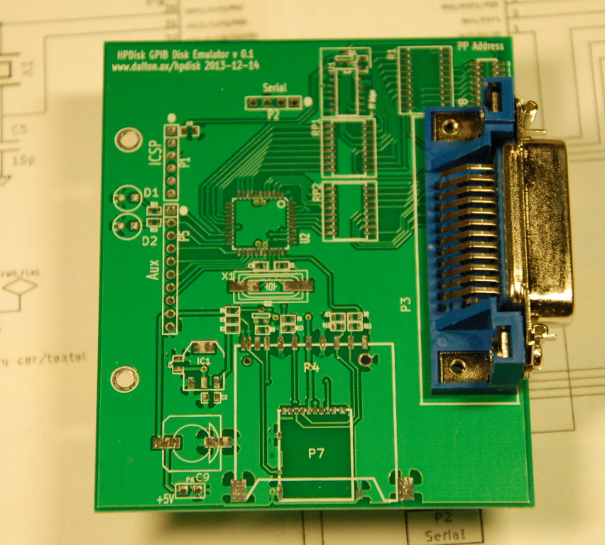
Alternative, using a GPIB female PCB connector. A male PCB should be mounted on the reverse side of the board. Note position of pin 1
We now have bare boards for sale. They are of professional quality, plated,soldermasked and silk-screened. Boards are available for both HPDisk and the Display/RTC board. The small profit I make on these boards helps me pay for further decelopment of HPDisk.
Note that the boards are indeed bare. You buy the components listed in the BOM and solder yourself. The board layout is designed to be hand-solderable, using a regular soldering iron with a fine tip.
HPDisk board: 25€ plus postage.
Display/RTCboard: 12€ plus postage.
HPDisk board + Display/RTCboard: 33€ plus postage.
Postage and packing to Europe is 6€ with priority mail. (march 2023)
Please send an email to projects@dalton.ax if you are interested.
Residents of the USA. I am currently unable to ship boards to the US because of the new De Minimis rules. See this article
Note that I cannot test with hardware I do not have and there is definitely a limit, both space-wise and money-wise, what I can test on. I currently test with the following:
HP 85 with the MS ROM
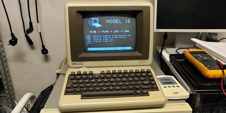
HP 9000/340 computer
HP 9816 computer
HP 3852A Measurement mainframe
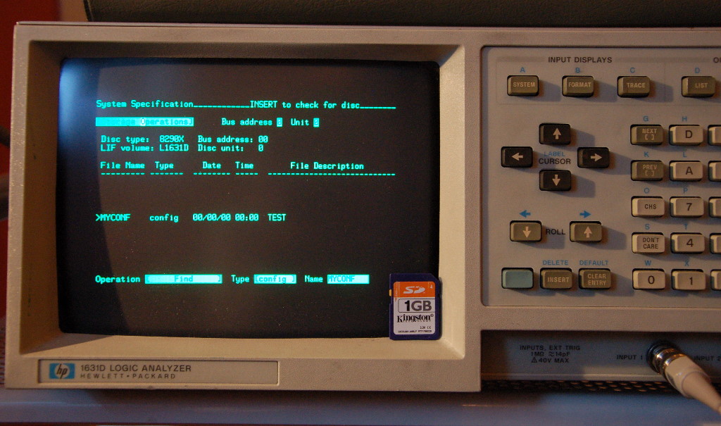
HP 1631D Logic Analyser
HP 35665A Audio Spectrum Analyser
Some of the above support Amigo, some support CS/80 and some support both.
The plain vanilla HP-85 is Amigo only and from what I know, this unit will work with HP-85 in Amigo mode if you have the mass storage ROM. It will also work in CS/80 mode if you have support ROMs (EMS ROM) for that, such as the PRM-85 ROM board from Bill Kotaska.
Everett Kaser has been kind enough to put together a small table that explains what is suported where. MS is the Mass Storage ROM. EMS is the extended Mass Storage Rom. Please click here for an in-depth explanation.
| Model | Amigo | SS/80 |
|---|---|---|
| HP83 | MS | N.A. * |
| HP85A | MS | N.A. * |
| HP85B | MS/ED built-in | 85 EMS |
| HP86A | MS built-in | 87 EMS |
| HP86B | MS built-in | 87 EMS |
| HP87A | MS built-in | 87 EMS |
| HP87XM | MS built-in | 87 EMS |
Please see the Wikipedia page on the HP-8X series for a good summary of what model does what.
I was finally able to lay my hands on a 9816 to test with. The unit has some hardware issues. Appears to have been stored in a very damp place. I have successfully booted BASIC 2,3,4,5, Pascal and CP/M68K in Amigo and CS/80 mode with both versions.
If anyone has a service manual for it, then please let me know!
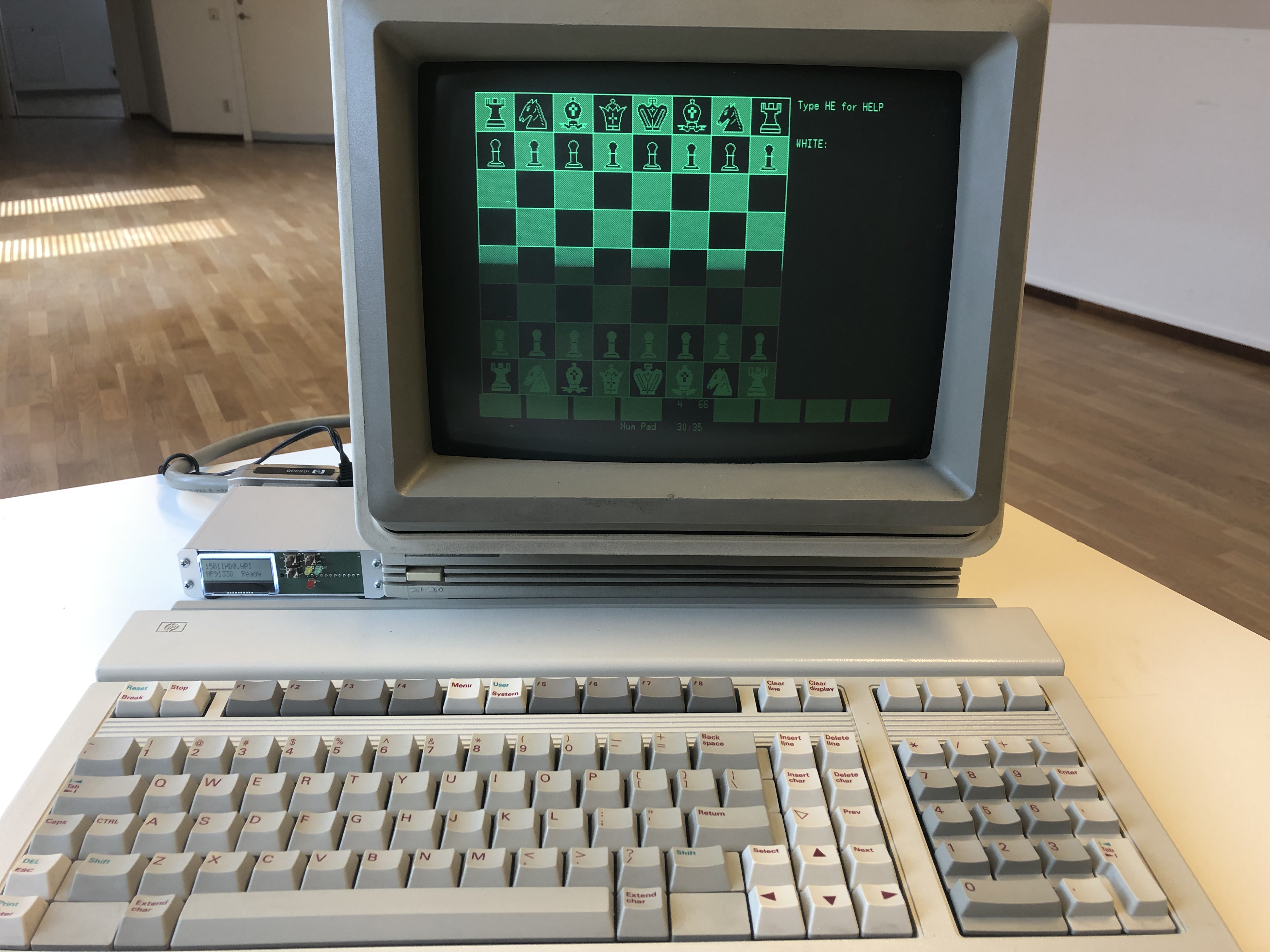
I have a HP 9000/340 to test with. I have successfully booted BASIC, Pascal, NetBSD 9.1 and HP/UX in CS/80 mode with the 46K40 version.
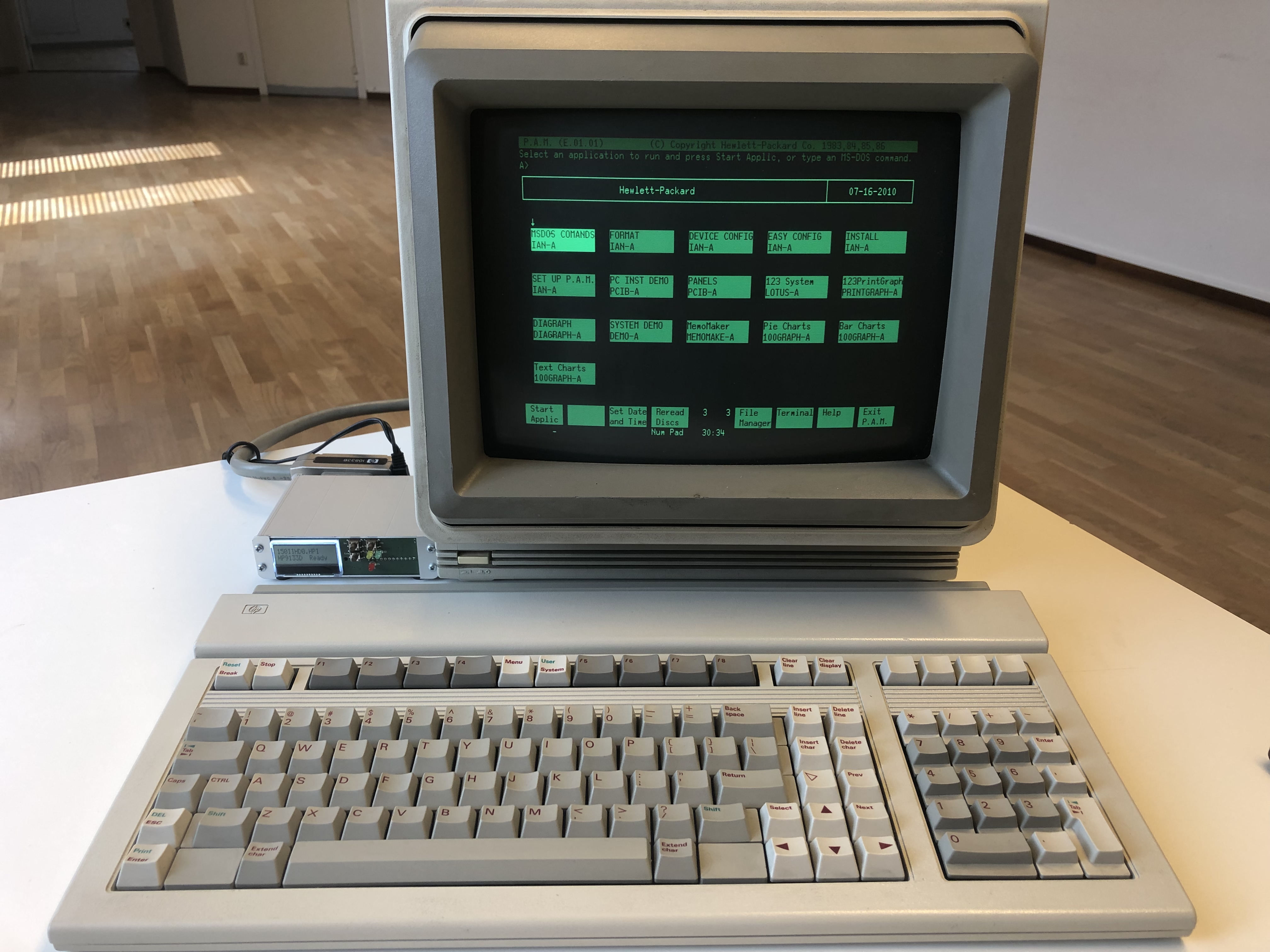
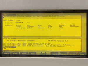
HPDisk has been tested with the Integral and the SYS V ROM in CS/80 mode. The SYS III ROM does not work for some reason. Note that Mattis Lind has a neat memory expansion board for the Integral in the making. You will find a zipfile with HPDisk files below.
I have been blessed with a HP 1000 A400 that runs RTE-A. The HP1000 or rather the 12009 HPIB interface is something of a challenge but I have a prototype version of the firmware running. I have realised that the current version will not work reliably. I am working on a new version that does.
One user has tested and confirmed that it works as expected.
The original design was created for measuring instruments and they were generally slow and not very picky on protocol implementations. Then people started using the design for computers as well, first the HP85, then HP98x6. The latter required some hardware changes and a complete rewrite of the GPIB reception to keep up. The MKII firmware now uses an interrupt-driven receiver that can accept and buffer up to 512 bytes of data whilst the rest of the code does other things.
There is an upgrade path, using the same PCB. You can remove the old processor and solder in a PIC 18F46K40. You can also remove capacitors C3, C5 and the crystal X1. If you want to use HPDisk with the HP98x6-series you also need to lower the value of R1 from 10k to 3.3k. Unfortunately does not anyone seem to have that value in stock, but you can either desolder R1 and substitute 17 3.3k resistors, alternatively solder in external 4.7k resistors from the GIPB data and control lines to +5V
Click image for larger image
You can also substitute a TXB0104 for the resistive dividers. Below is a picture from Chimin Mao who did just that. This will speed up the maximum allowable clockrate for the SD card and you can run with CLK 0 in HPDISK.CFG
p>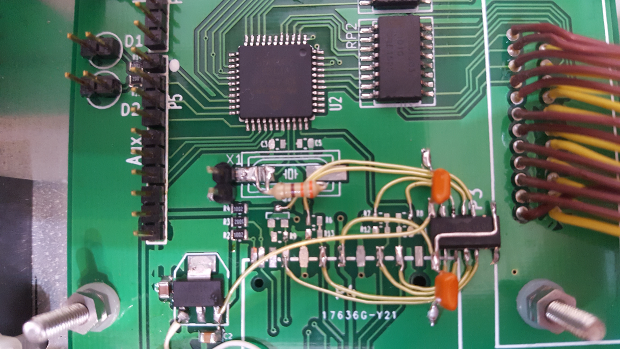
Use the MKII schematic as reference and remove R6,R7,R8, R11,R12,R13,R4, R9 and Q2. Then connect the TXB0104 as per the MKII Schematic.
Going forward in 2020 there will be two branches of firmware. One for the PIC184620 processor and one for the PIC1846K40. They both work with the same PCB
Those familiar with my GPIB Adapter will recognise the code, even if the gpib.* files are cleaned up extensively. All pin assignments are now done through #defines so it should be fairly easy to change around pins or port to another PIC. A word of caution though: You need a 5V capable PIC that has ports that can sink 25mA in case you have more than a handful instruments on the bus.
One difference from the GPIB adapter is that gpib.c calls amigo.c or ss80.c for every received byte (The MKII version buffers in a ring-buffer), this is because we need to be able to act on a command sequence when it happens. The received byte is pushed into a finite-state-machine where the Amigo or SS/80 protocol is decoded. If a valid command has been detected a status > 0 is returned to GPIB which stops reception and the appropriate command is executed. Adding commands is easy: Just add the decoding to the finite -state-machine, add a return code and a handler for that command.
The latest source is posted below
2018-03-25: Corrected a number of issues with the Amigo emulation. This firmware does work correctly for storing and loading in Amigo mode on my HP1631D. Sadly, that is the only Amigo-capable unit I have, so I cannot test further. If you run into issues with Amigo, then please program with the debug firmware and send me logs.
2016-11-18: The fall FW now works correctly with the HP85 computer (SS80 only) and adds a new feature: You can have up to 8 disk images and select which one with a suitable BCD Switch.
2020-01-25: I have ported back the MKII code to run on the 18F4620. It is basically the same code as far as protocol goes, but the gpib routines and interrupts are completely rewritten. I have tested this with the HP1631D and HP3852A. It does not work with the 9816 though. This firmware also supports up to 16 files for disk 0 and an additional three as disk 1..3.
To activate the disk select feature, you must add DSKSEL 1 to hpdisk.cfg. The FW will then poll the lower three bits on PORTE (pins 6,7,8 on AUX), plus 5 and select between files lifdata0.bin, through lifdataf.bin. A suitable hardware consists of a binary or BCD switch that pulls up those pins through a 10k resistor. You also need pulldowns, say 100k per pin.
The 18F46K40 has built in weak pullups so with that FW you can get away with just a switch with common connected to ground. In that case, use DSKSEL 2. The AUX pin weights are the same in both cases. Pin 6 = 1, Pin 7 = 2, Pin 8 = 4, Pin 5 = 8.
2020-02-22: Added support for the display piggyback board. Use DSKSEL 3 for that.
2020-04-21: v0.11 Corrected two bugs that only happened when you had two separate disk units on the same GPIB bus. In that case some operations, such as copying from one unit to another would fail.
2020-09-14: v0.13 Koskenkorva edition. Fixed a nmber of bugs. Made disk parameters settable through describe.cfg flr SS/80. Made SD-card clock speed settable. Note that speeds above 1MHz requires active level shifters.
2020-11-29: v0.15 Fixed a number of bugs. There was a nasty one affecting writes, one that only surfaced when used with HP VNAs
2021-01-11: v0.16 Fixed a number of issues pertaining to the HP-85. The HP85 has several peculiarities in its HPIB-implementation. This version works with a pure HP85B (with HPIB module only) in Amigo mode and in CS/80 mode if you have the PRM-85 with EMS ROM.,
2021-04-22: v0.18 Upgraded FatFS to v0.14. Changed display of Vectors (QWORD). Added self-test routine: Debug 255 first checks PP machinery, then loops displaying pin status. Corrected the handling of the AUX port in case we have no or mechanical switch. SDC Should only issue clear command if selected. Added support for 0x14 Request Address. Brownout interrupt changed from 2.45 to 2.85V. If the disksel byte from EEPROM is 0xff it is set to 0 not masked to 1f. If filename pointed to byt diskno is blank, increment and try next. RTC now returns a HP8X REAL if you set RTC to 2. Speedup of GPIB transmit.
2021-06-06: v0.19 Corrected some issues reading describe.cfg. Now supports the separate disk number that can be given as part of transparent commands. Now correctly returns a module_address error for nonexistent units. HP9000/425 would loop inifinitely if not. Tested with NetBSD 9.1 on 9000/340 and 9000/425.
2021-07-08: v0.20 Many thanks to Izumi Tsutsui for testing. Separate describe-blocks for all 4 disks. Disk 1..3 are now 0x81..3 in describe.cfg. Handles unit numbers sent as part of transparent commands correctly. Turn off all slew rate limiting. This allows us to run the SPI at 16MHz (CLK 0). SendGPIB now in assembly which makes it quite a bit faster, faster than my 9000/340 in fact, expect to see > 100kb/s. Changed the GPIB handshaking so that we assert NRFD on buffer full and deassert on half full. Tested with NetBSD 9.2 on 9000/340 and 9000/425.
2021-12-05: v0.22 Fixed an issue with the set addressing mode (0x48) that was incorrectly handled. Changed the GPIB lines from schmitt-trigger to TTL level as some units did not quite make the high level needed.
2022-11-06: v0.24 Changed so that we can handle blocksizes other than 265 for things like the 9122 floppy that can be formatted as 256/512/1024. There is no way to embed this info in a straight image file, so you need to change the parameters in describe.cfg and have different "floppies" for different sector sizes. HPDISK.CFG now has an additional parameter for troubleshooting: TRG. If you put in say TRG 123 then the trigger output (A6/TP1) will start outputting pulses after the 123rd QSTAT. This is handy to trigger logic analysers. Note that this FW has issues on slow hosts. setting DEBUG 1 in hpdisk.cfg usually helps.
2023-11-21: v0.26 Fixed a number of bugs: There is now a 600us delay on each command in Amigo to help with issues on the HP85. Changing the disk image now sets QSTAT to 2 and raises a power fail. Without this the host may not notice that you have changed disk image through the front panel and write cached data to the wrong disk. There was also a bug where we would go to CS80 Execution state even if not addressed. This only showed up when you had multiple disks on different addresses. The logic to read to end if no length was given would fail and cause any read less than 0x100 bytes to fail. On slow hosts we need to wait for ATN to deassert before doing stuff indicated by execute
2024-01-31: v0.27 Fixed some bugs: 1. The logic to read to end if no length was given would fail and cause any read less than 0x100 bytes to fail 2. On slow hosts we need to wait for ATN to deassert before doing stuff indicated by execute.2025-02-25: v0.28a Fixed some bugs mostly related to Amigo: 1. The older versions would not parse the config files correctly if they were created on a mac. Changed the logic so that it accepts LF or CR. 2. Fixed some issues only happening on HP9845. 3. Made the Amigo parameters settable through AMIGO.CFG. 4. Signal drive not connected if image file cannot be opened. 5.Set DSJ to 1 on seek errors. Tested with the HP9845.
Note on the various debug versions. They are all identical, except how much debug output they provide, but naturally does the debug output affect timing. It also slows down things. I generally recommend that you run with the "sdebug0" version for production, as it is faster. Sdebug 0 means "nothing but bytes", 1 means bytes and commands, 2 is bytes, commands and dump of all records read or written.
Beginning with version 0.27 all code is consolidated and built from the same sources. That is versions for the 4620, 46K40 and 47K42. The 47K42 has twice the program space so I have been able to squeeze in a bootloader. With that the firmware can be upgraded from a file on the SD-card itself.
2014-02-24 Firmware for both hardware and software parallell poll
2016-11-18 firmware for hardware parallell poll only
2018-03-23 Debug firmware for hardware parallell poll only
2018-03-25 Firmware for hardware parallell poll only
You will need a PIC programmer to program updated firmware, unless you have the PIC1847K42 version with bootloader. I, myself use Microchip's PICKit, but I have had reports of users having good results with the JDM Programmer and PICPgm
Firmware supports parallell poll only
Firmware currently in beta. Will post source files soon. This FW has been tested with the HP85, HP9816, HP9000/340, HP9000/425, HP35665A, HP1631D, HP3852A, HP8752A
Beta MKII (2020-01-25) firmwareFirmware supports parallell poll only
This is the bootloader version. Ie FW can be upgraded from a file on the SD-card. The file itself is created from the HEX-file, but formatted in such a way that it is easier to read from the booloader. The bootloader looks for HPDISK.FW so rename the file before putting it on the SD card.
The 0.5 bootloader now shows errors on the display, not just over serial
v0.4 MKII (2024-11-01) bootloader for the PIC18F47K42.The binary data encoded from the hex file is: Data is written as 256+16 byte records as follows: AAAAPPcccbbbbbbb..........b Where AAAA = 32 bit address in PIC format lsb .. msb PP = pagesize c = checksum bbbb = PAGESIZE bytes
To program just use your favourite tool to program the bootloader. Then put the jumper in the PROG position. Insert an SD card with the FW file and power up. The bootloader should program and show progess on the display. When done, power off. Move the jumper to RUN and power up.
This project is going on 10+ years and there has been considerable interest with over 100 of these units built. I have revised the PCBs over the years, trying to retain backward compatibility. The different revisions are summarised below:
See errata below.
See errata below.
Board redesigned to fit in cases designed for 100mm wide cards. All connectors placed on one edge and leds/display on the other. Polarity reversal and overvoltage protection. Active level translators for the SD card.
Board adjusted to fit in a Hammond 1455 box (Mouser 546-1455L801). Changed the 3.3V regulator.
Board layout adjusted adding footprints for a small HEX switch and an alternative, standup LED. This is for those that do not want/need the display board. Added a boot jumper for the PIC18F47K42 bootloader and improved the cooling for the 5V regulator. Other than that the board is the same
The PCB is laid out so that it should be hand-solderable. I am no spring chicken, but I solder the boards with a regular Weller iron with a 0.3mm tip and 0.3mm solder. Having a stereo microscope helps. I also use a flux pen on all IC footprints.
Take care to note the orientation of all ICs. Pin 1 is marked on the footprint silk-screen and also with a small dot or rectangle next to pin 1. It is generally best to get the oriantation right the first time as desoldering is a royal pain.
Note that the current firmware reads configuration data from a file named hpdisk.cfg on the SD card. The format is very simple: Lines with KEYWORD-VALUE pairs one space between. This way the desired protocol (Amigo or SS/80) can be selected. The config file is read on startup and when changing disks. The structure of the image file is the same for both Amigo and S/80, ie you can easily read an image created with Amigo, on a SS/80 system.
Please be aware that the parser that reads the config files is rather brain-dead. Use straight ascii and DOS/Windows line endings. Ie use something like notepad to edit it
| Option | Explanation | Supported in |
|---|---|---|
| PROTO | Protocol used 0=Amigo, 1=SS/80 | |
| DEBUG | Debugging, 1 shows individual bytes. 128 does a selftest, then loops and displays port status | 0.16 |
| DSKSEL | Activates disk select on AUX 5,6,7,8. 1 means pulldowns and connect to +5V, 2 means built-in pullup, connect to ground. 3 is for the piggyback board | |
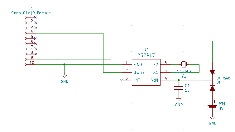
| RTC | If 1 or 2 then HPDisk reads time from a DS2417 on AUX 4. Controlled trough a file called RTC on disk image. See below for examples. | 0.9 |
| NAMEx | Where x is 0..F, File names for the image files selectable for drive 0. Names should be 8.3 format. | 0.9 |
| DISKx | Where x is 1..3, File names for the image files for drive 1..3. Names should be 8.3 format. | 0.9 |
| CLK | Where x is 0..90, Sets the speed of the SPI clock. 0 is 16MHz, 1 is 4MHz, 2 or 20 is 1MHz. Anything below 25 requires active level-shifters for SPI | 0.13 |
| TRG | Where x is a number, Activates trigger pulses on TP1 after x occurrences of QSTAT | 0.24 |
| ADDR | Where x is a number 0..7, sets the HPIB address | 0.27 |
Amigo is a bit braindead in that it required the computer to know the geometry of every drive, even those that have not been made yet. CS/80 fixes that by having a call called DESCRIBE that returns everything you need to know about the drive. In HPDisk you realise this through an optional file, decribe.cfg. The first value is the disk for which you intend the values. After that the two ID bytes and the rest are disk parameters. A value of 7F is wildcard and will apply to every disk that does not have settinfgs defined. 81..83 are the entries for the three fixed disks, unit 1..3. The example below shows disk 0 as HP9122B, disk 5 as HP7953C and all the rest as HP9122A.
7F 02 22 80 01 02 E8 05 01 09 12 20 01 00 01 00 17 00 00 2D 11 94 20 D0 0F 00 01 00 00 4F 01 00 0F 00 00 00 00 09 FF 00 HP9122A
00 02 22 80 01 02 E8 05 01 09 12 20 01 00 01 00 17 00 00 2D 11 94 20 D0 0F 00 01 00 00 4F 01 00 0F 00 00 00 00 09 FF 00 HP9122B
05 02 2d 80 07 03 E8 00 00 07 95 81 01 00 40 00 01 00 03 00 00 50 01 F4 01 01 00 00 06 23 05 00 3E 00 00 00 09 11 27 00 HP7953C
the fields are as follows
;   First ID Byte
;   |  Second id byte
;   |  |  Controller description
;   |  |  Always 0x80
;   |  |  |  Number of units
;   |  |  |  |  Transfer rate
;   |  |  |  |  |     Controller type
;   |  |  |  |  |     |
;   |  |  |  |  |     |  Unit description
;   |  |  |  |  |     |  Unit type
;   |  |  |  |  |     |  |  Type 091220
;   |  |  |  |  |     |  |  |        Bytes per block (0x100)
;   |  |  |  |  |     |  |  |        |     Number of byúffered blocks
;   |  |  |  |  |     |  |  |        |     |  Burst size
;   |  |  |  |  |     |  |  |        |     |  |  Block time in us (1700)
;   |  |  |  |  |     |  |  |        |     |  |  |     Continous transfer rate = 002dh = 45
;   |  |  |  |  |     |  |  |        |     |  |  |     |     Optimal retry 4500 = 0x1194
;   |  |  |  |  |     |  |  |        |     |  |  |     |     |     Access time 8400 = 0x20d0
;   |  |  |  |  |     |  |  |        |     |  |  |     |     |     |     Maximum interleave
;   |  |  |  |  |     |  |  |        |     |  |  |     |     |     |     |  Fixed volume byte (no fixed volumes)
;   |  |  |  |  |     |  |  |        |     |  |  |     |     |     |     |  |  Removable volume byte
;   |  |  |  |  |     |  |  |        |     |  |  |     |     |     |     |  |  |
;   |  |  |  |  |     |  |  |        |     |  |  |     |     |     |     |  |  |  Volume description
;   |  |  |  |  |     |  |  |        |     |  |  |     |     |     |     |  |  |  Max cylinder 0x4f
;   |  |  |  |  |     |  |  |        |     |  |  |     |     |     |     |  |  |  |        Max head
;   |  |  |  |  |     |  |  |        |     |  |  |     |     |     |     |  |  |  |        |  Max sector = 15
;   |  |  |  |  |     |  |  |        |     |  |  |     |     |     |     |  |  |  |        |  |     Max single vector address 09ff00
;   |  |  |  |  |     |  |  |        |     |  |  |     |     |     |     |  |  |  |        |  |     |                 Current interleave
;   |  |  |  |  |     |  |  |        |     |  |  |     |     |     |     |  |  |  |        |  |     |                 |
7F 02 22 80 01 02 E8 05 01 09 12 20 01 00 01 00 17 00 00 2D 11 94 20 D0 0F 00 01 00 00 4F 01 00 0F 00 00 00 00 09 FF 00 HP9122
02 02 2d 80 01 03 E8 00 00 07 95 81 01 00 40 00 01 00 03 00 00 50 01 F4 01 01 00 00 06 23 05 00 3E 00 00 00 09 11 27 00 HP7958B
The last text value is conveniently shown on the display (if attached)
Note that you can create a completely arbitrary disk type this way. The file BigDisk.zip contains a bootable 900Mb floppy with BASIC 5.1
PetitFatFS is limited to FAT16, ie max 2Gb so a small SD card is preferable. Format as FAT16 and put two files in the root: hpdisk.cfg and lifdata.bin. The latter can be the sample above or just and empty file,large enough. Note that Micro SD-cards do not have a write protect switch. To be able to write you will need to jumper pin 11 on the big SD-card footprint to ground.
The MKII firmware uses FatFS instead which supports FAT32, more open files etc.
The MKI source is compiled under MPLAB 8.92. The MKII using MPLABx and XC8 v2.10
Latest MKI (2014-01-08 v0.6) files. I kindly ask anyone who fixes bugs or makes improvements to send me the files so I can incorporate it in the main project
Latest 18F46K40 MKII (2020-03-05 v0.10) files.
The hP 98x6 series computers has a fairly accurate internal clock and several nice hooks in RMB (Rocky Mountain Basic) to fire off events based on current time. They do not have any battery backup though, so you need to set the time every powerup. That is why I created this little addon that plugs into the AUX socket of HPDisk.
With fw 0.10 or later you just create a BDAT file on the disk (image). The file needs to be in the first part or the directory as I will only search the first sector of the directory. If that file is present and you have added "RTC 1" to the CFG-file, HPDisk will take note of that and every time you read the BDAT file you will get the data as four integers from the DS2417. If you write four integers to that file, you set the clock.
You can then have an AUTOST program that reads the time when you power up your computer and a small program to set time
Set time
10    INTEGER B1,B2,B3,B4
20    REAL Start,Now,R1,R2,R3,R4,V
30    CLEAR SCREEN
40    PRINT "WELCOME - PLEASE SET TIME"
50    !CREATE BDAT "RTC",1
60    Start=DATE("1 JAN 2000")
70    LINPUT "ENTER DATE AS 1 JAN 2020",D$
80    LINPUT "ENTER TIME AS HH:MM:SS",T$
90    SET TIMEDATE DATE(D$)+TIME(T$)
100   Now=TIMEDATE-Start
110   R4=Now DIV 16777216
120   V=Now MOD 16777216
130   R3=V DIV 65536
140   V=V MOD 655366
150   R2=V DIV 256
160   R1=V MOD 256
161   B4=R4
162   B3=R3
163   B2=R2
164   B1=R1
170   ASSIGN @File TO "RTC"
180   OUTPUT @File,1;B4;B3;B2;B1
190   PRINT "WROTE B4:";B4;" B3:";B3;" B2:";B2;" B1:";B1
200   ASSIGN @File TO *
210   PRINT Now
220   ENDN
Autost
1     INTEGER B4,B3,B2,B1
2     REAL Start,Now,R4,R3,R2,R1
10    CLEAR SCREEN
20    PRINT "WELCOME - SETTING TIME"
60    ASSIGN @File TO "RTC"
70    ENTER @File,1;B4;B3;B2;B1T
71    PRINT "READ B4..B1 ";B4;" ";B3;" ";B2;" ";B1
72    Start=DATE("1 JAN 2000")
73    R4=B4
74    R3=B3
75    R2=B2
76    R1=B1
78    Now=Start+R4*16777216+R3*65536+R2*256+R1
80    ASSIGN @File TO *
90    PRINT Now
100   SET TIMEDATE Now
101   PRINT DATE$(TIMEDATE);" ";TIME$(TIMEDATE);
110   ENDN
Note that I quite arbitrarily chose Jan 1 2000 as zero to give me a manageable 32-bit value. Internally the 98x6 stores time as a double-precision REAL. I also used four integers as the 98x6 does not have unsigned integers
RTC 2 is for HP8x, ie HP85, HP86, HP87. It works the same way, but passes the datetime as a HP REAL
This small board plugs into the AUX connector and adds an RTC plus a 16x2 display and buttons to select disk image files.
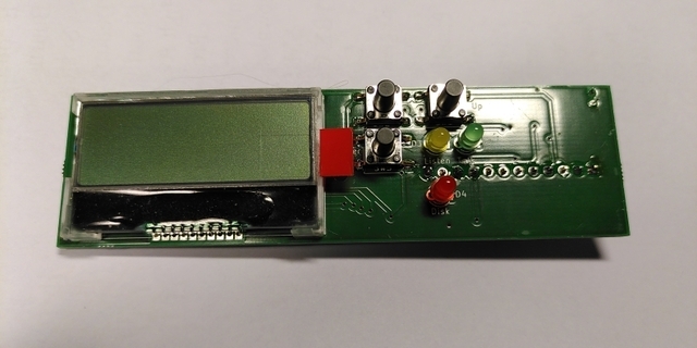
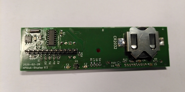
Supported in MKII firmware 0.10 or later.
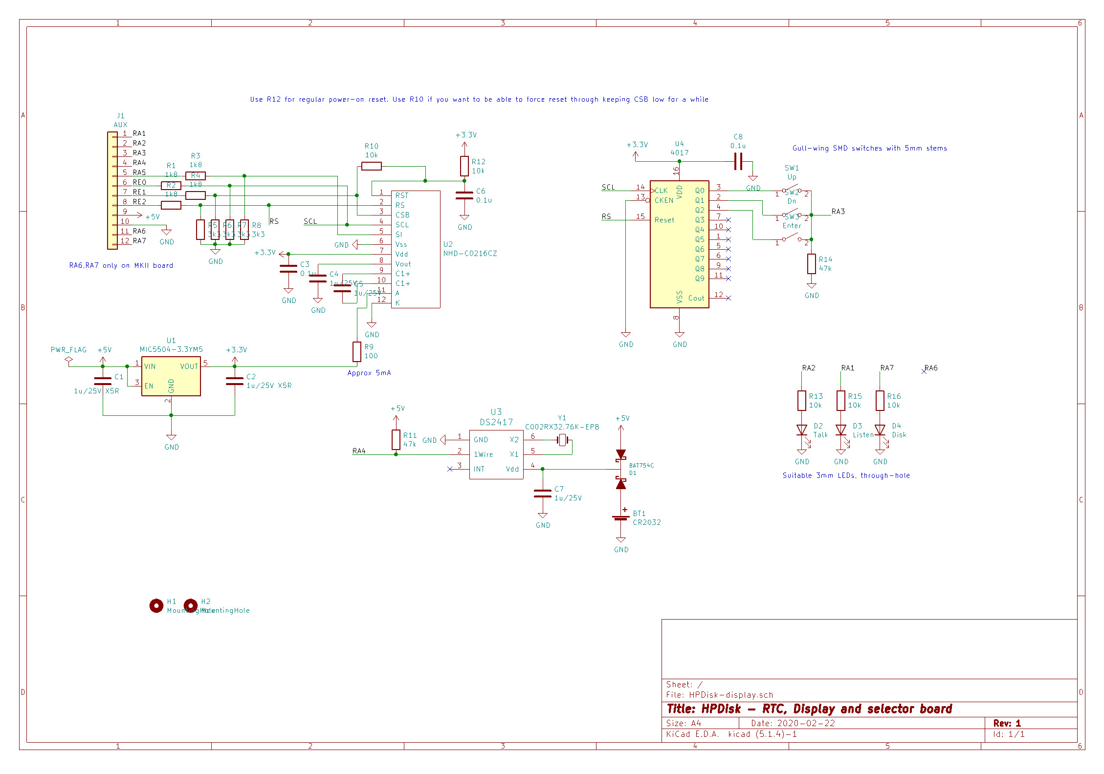
Note that the piggyback board has two extra pins to accomodate possible extra functions on future MKII PCBs. You can ignore those and just fit a 10-way header if you have the original HPDisk board
Download the desired versions of lifdata.bin and hpdisk.cfg and copy to the root of the SD card. Jumper PP to address zero (corresponds to HPDisk being unit zero). Insert card and boot up HPDisk. The firmware will try to mount the card, read hpdisk.cfg and then start polling GPIB. If the mounting or opening of the image file fails, LED1 will blink an error code. Count the number of short flashes before the long. That is the code (1..17). Codes are straight from FatFs:
| Error | Code |
|---|---|
| FR_OK | 0 |
| FR_DISK_ERR | 1 |
| FR_NOT_READY | 2 |
| FR_NO_FILE | 3 |
| FR_NOT_OPENED | 4 |
| FR_NOT_ENABLED | 5 |
| FR_NO_FILESYSTEM | 6 |
| FR_DENIED | 7 |
| FR_EXIST | 8 |
| FR_INVALID_OBJECT | 9 |
| FR_WRITE_PROTECTED | 10 |
| FR_INVALID_DRIVE | 11 |
| FR_NOT_ENABLED | 12 |
| FR_NO_FILESYSTEM | 13 |
| FR_MKFS_ABORTED | 14 |
| FR_TIMEOUT | 15 |
| FR_LOCKED | 16 |
| FR_NOT_ENOUGH_CORE | 17 |
| FR_TOO_MANY_OPEN_FILES | 18 |
| FR_INVALID_PARAMETER | 19 |
If you see a return code of 7, then something is wrong at a lower level. Common causes are not having a BSH103 as Q2 or ripple on the power line.
If the disk ops are OK, both leds will start flashing, indicating GPIB activity.
For more serious troubleshooting, ie if you find that the unit does not work with your HP Super Whizzo, then I need you to program with a debug build and then grab the debug output from the serial port. Send me that data and I promise to look at it. I cannot promise to fix the problem, but I will try. The serial port is P2 and outputs data at 38400 baud (115200 for the MKII versions). It is TTL level so you need a TTL-RS232 level shifter (max232) or an USB to TTL converter. The latter can be found on eBay for a dollar or two.
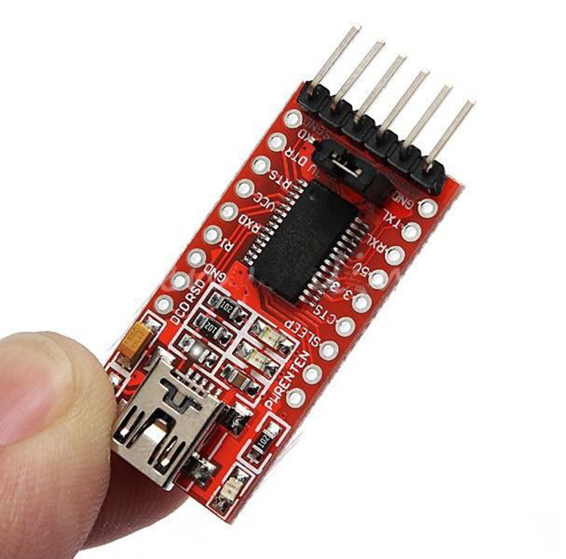
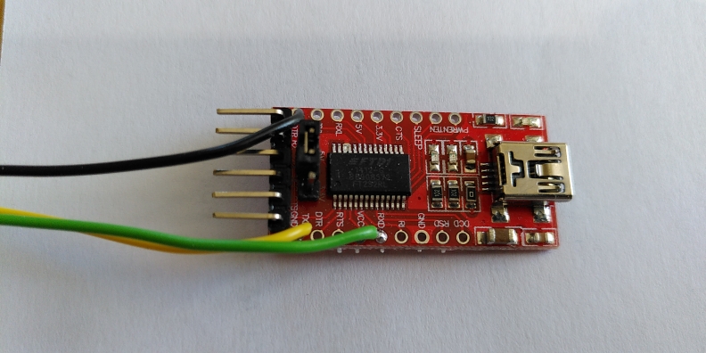
Note that you only need to wire three pins as the adapter is powered from USB. Note also that that particular adapter has a jumper to set 3.3V or 5V operation. It should be set to 5V.
| Pin | Function |
|---|---|
| 1 | Data out, connect to RXD on adapter |
| 2 | Data in, connect to TXD on adapter (Not currently used) |
| 3 | Ground, connect to ground on adapter |
Please note this! The microcontroller on the board has protection diodes on the inputs that will feed any voltage ebove Vcc (5v in this case) to Vcc.If you turn off the PSU to the unit whilst it is still connected to the host (your measuring device in this case), the voltage on the GPIB bus will be enough to feed the card, but not reliably. This will make HPDisk appear dead.
This is just a collection of useful links relating to HP disk protocols.
Note that there are two revisions of the PCB. The original one and the b-revision from April 2016.
The footprint on the Hirose Micro-SD connector is wrong. Use a regular size SD-connector
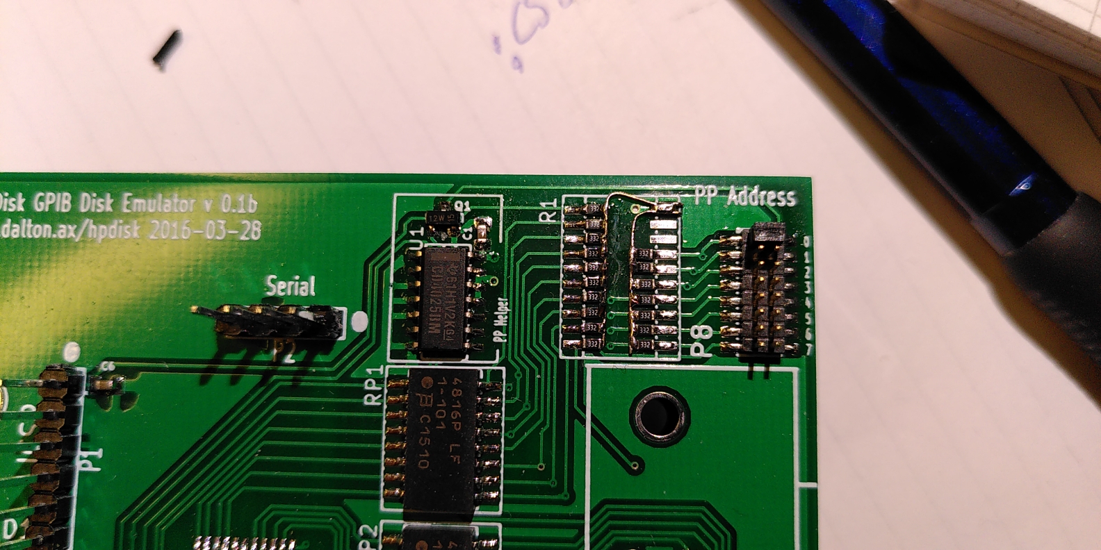
The silkscreen for the resistor packs is not clear when it comes to orientation, but all three should be oriented the same way as the IC marked U1
The large pads for the large SD connector are not connected to ground. They should be, or card detect and write protect will not work. Solder a wire from the SD Card holder body to ground
Micro SD-card holders do not have a write-protect switch. If you use a Micro-SD, you need to jumper pin 11 on the big SD-card footprint to ground.
The markings on the on-board leds (not needed if you have the display are the wrong way around.
The pin 1 markings are somewhat illegigible on the silkscreen. They should look like this:
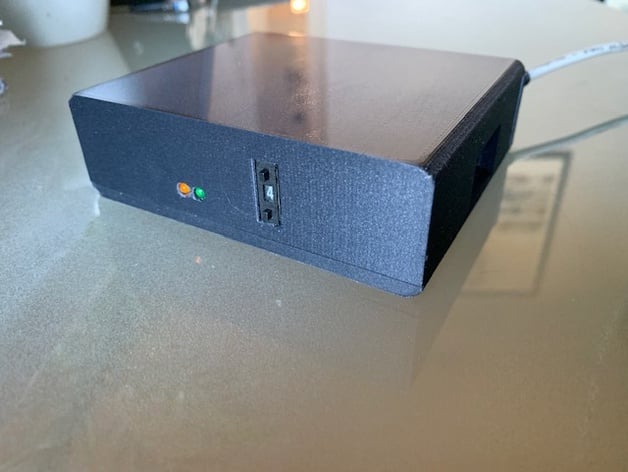
Someone made a really neat 3D printed box for the original HPDisk see
!
Here is another, suitable for the MKII boards. Note that it has the display board mounted flat on the main PCB which is also an option. Just make sure you provide insulation.
Martin Zumr from the Czech Republic has made this video
showing HPDisk in action on his HP-85 computer. Enjoy!
This is what to expect in the way of blinking leds this video. This is with the old FW. The new FW use the leds differently. One is TALK and thee other is LISTEN.
Proper HPIB cables have locking screws with an odd thread. Suitable nuts can be ordered from your favourite distributor 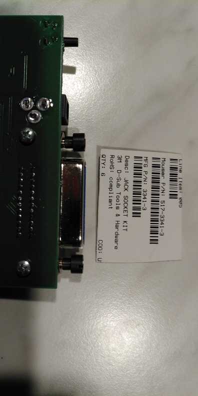
This information and the circuits are provided as is without any express or implied warranties. While every effort has been taken to ensure the accuracy of the information contained in this text, the authors/maintainers/contributors assume no responsibility for errors or omissions, or for damages resulting from the use of the information contained herein. I disclaim everything. The contents of the articles below might be totally inaccurate, inappropriate, or misguided. There is no guarantee as to the suitability of said circuits and information for any purpose whatsoever other than as a self-training aid. I.E. If it blows your equipments, trashes your hard disc, wipes your backup, burns your building down or just plain don't work, IT ISN'T MY FAULT. In the event of judicial ruling to the contrary, any liability shall be limited to the sum charged on you by us for the aforementioned document or nothing, whichever is the lower. I will not be held responsible for any damages or costs which might occur as a result of my advice or designs. Nor are you allowed to use any of my designs for commercial purposes without my written authorisation.
